

Flexible color filter substrate using phase change ink and preparation method thereof
A color filter, flexible substrate technology, applied in nonlinear optics, optics, optical components, etc., can solve problems such as the inability to achieve uniform color, and achieve the effect of reducing light leakage and excellent optical properties
- Summary
- Abstract
- Description
- Claims
- Application Information
AI Technical Summary
Problems solved by technology
Method used
Image

Examples
Embodiment 1
[0097] 40wt% red dye ( red395), 30wt% trimethylolpropane triacrylate (TMTPA), 20wt% dipentaerythritol hexaacrylate (DPHA) and 10wt% phase change material (C 22 OH) were mixed to prepare a phase change ink composition with a melting point of 65°C.
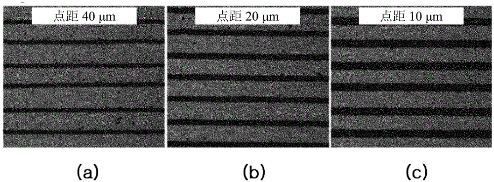
[0098] After injecting the above-mentioned phase-change ink composition into the reservoir, the temperature of the reservoir was set to 75° C., and a voltage of 80 V was applied thereto using an HM-30 print head (manufactured by Dimatix. Inc., discharge volume: 30 pl). The spray is carried out through all 256 nozzles. This discharge was performed on a PET film (manufactured by Lamiace Corp.), and during the discharge, the dot pitch was set to have an interval of 40 μm. After ejection, a line pattern with an average line width of about 50 μm and an average line height of 14 μm was formed. image 3 A shows the shape of the formed pattern after ejection.
[0099] Next, the above-mentioned pattern was pressed using a pressure rolle...
Embodiment 2
[0101] Discharging was performed in the same manner as described in Example 1 except that the dot pitch was set to have an interval of 20 μm, thereby forming a line pattern having an average line width of about 70 μm and an average line height of 20 μm. image 3 B shows the shape of the formed pattern after ejection.
[0102] Next, the above-mentioned pattern was pressed using a pressure roller under the conditions of 60° C. and 0.1 MPa, and the pattern was flattened. Figure 4 B shows the pattern shape after pressing. refer to image 3 B and Figure 4 B, It can be confirmed that the line width of the pattern is widened after pressurization. The line width and line height of the pattern before and after pressing are described in [Table 1] below.
Embodiment 3
[0104] Discharging was performed in the same manner as described in Example 1 except that the dot pitch was set to have an interval of 10 μm, thereby forming a line pattern having an average line width of about 90 μm and an average line height of 28 μm. image 3 C shows the shape of the formed pattern after ejection.
[0105] Next, the above-mentioned pattern was pressed using a pressure roller under the conditions of 60° C. and 0.1 MPa, and the pattern was flattened. Figure 4 C shows the pattern shape after pressing. refer to image 3 C and Figure 4 C, It can be confirmed that the line width of the pattern is widened after pressurization. The line width and line height of the pattern before and after pressing are described in [Table 1] below.
[0106] [Table 1]
[0107]
[0108] pass image 3 , Figure 4 And [Table 1], it can be confirmed that in the case of using the phase change ink composition to form a pattern (as in the embodiment of the present invention), t...
PUM
 Abstract
Description
Claims
Application Information