
Conductive paste composition for solar cells

A solar cell and conductivity technology, applied in the field of conductive paste composition, can solve problems such as contact resistance reduction

Inactive Publication Date: 2014-05-14
NORITAKE CO LTD
View PDF12 Cites 4 Cited by
  • Summary
  • Abstract
  • Description
  • Claims
  • Application Information

AI Technical Summary

Problems solved by technology

In addition, since Li is a donor element, it also has the effect of reducing the contact resistance.

Method used


Image

  • Conductive paste composition for solar cells
  • Conductive paste composition for solar cells
  • Conductive paste composition for solar cells

Examples


Embodiment Construction

[0058] Hereinafter, an embodiment of the present invention will be described in detail with reference to the drawings. Furthermore, in the following embodiments, the drawings are appropriately simplified or deformed, and the dimensional ratios and shapes of each part are not necessarily accurately drawn.

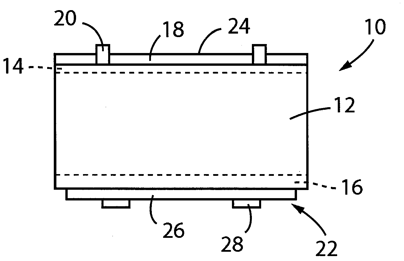
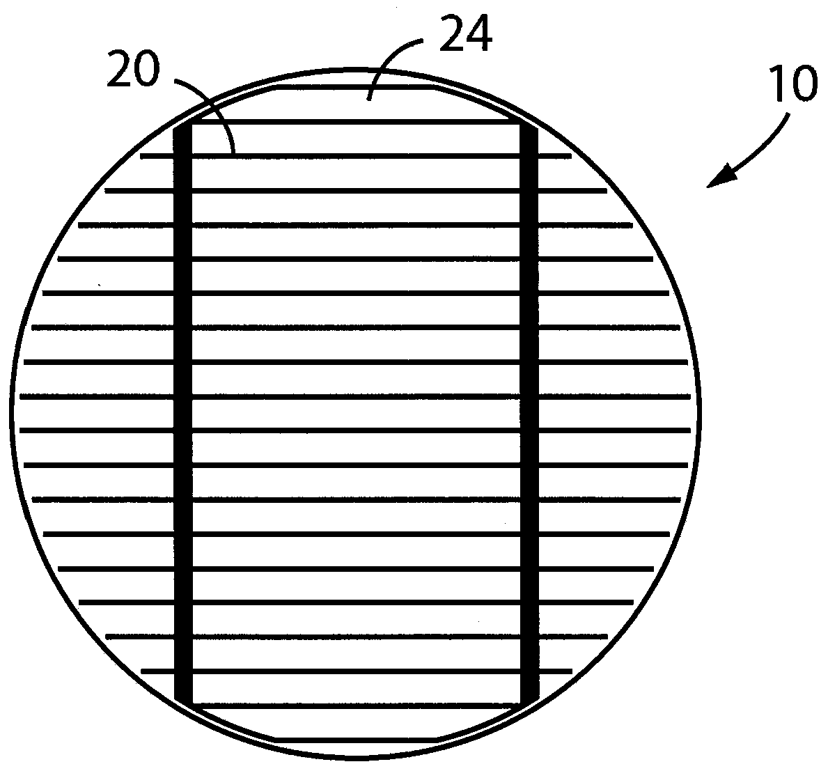
[0059] figure 1 It is a diagram schematically showing a cross-sectional structure of a silicon-based solar cell 10 to which a conductive composition according to an example of the present invention is applied. figure 1 Among them, the solar cell 10 includes, for example, a silicon substrate 12 that is a p-type polycrystalline semiconductor, and an n layer 14 and a p layer formed on the upper and lower surfaces thereof, respectively. + layer 16, the anti-reflection film 18 formed on the n layer 14 and the light-receiving surface electrode 20, on the p + A rear electrode 22 is formed on layer 16 . The thickness dimension of the silicon substrate 12 is, for example, about 10...


PUM

PropertyMeasurementUnit
particle diameteraaaaaaaaaa
viscosityaaaaaaaaaa

Abstract

Provided is a conductive paste composition for solar cells that makes it possible to simplify control of the penetration amount of an electrode material during the fire-through process, and to easily obtain an ohmic contact. The solar cell (10) has a light-receiving surface electrode (20) formed by the fire-through method, and the light-receiving surface electrode (20) is configured from a thick-film silver containing glass that contains SO2 in the amount of 0.05-5.0 mol%; hence, the thick-film silver paste reduces viscosity when the glass softens while maintaining favorable corrosion resistance, without adding alkali metals such as Li, Na and K, or changing the composition. Therefore, a thin, uniform glass layer is formed at the interface between the light-receiving surface electrode (20) and an n-layer (14); hence, it is possible to obtain a solar cell having excellent electrical properties.

Description

technical field [0001] The present invention relates to a conductive paste composition suitable for solar cell electrodes formed by a fire through method. Background technique [0002] For example, a general silicon-based solar cell has a structure in which an n + The layer has an anti-reflection film and a light-receiving surface electrode, and, under it, a p + The layer is equipped with a back electrode (hereinafter, simply referred to as an "electrode" when not distinguishing between them), so that the electric power generated at the pn junction of the semiconductor by light reception is taken out through the electrode. The anti-reflection film is a film for ensuring sufficient visible light transmittance, reducing surface reflectance and improving light receiving efficiency, and includes thin films of silicon nitride, titanium dioxide, silicon dioxide, and the like. [0003] Since the antireflection film has a high resistance value, it hinders efficient extraction of e...

Claims


Application Information

Patent Timeline
Patent Type & Authority Applications(China)
IPC IPC(8): H01L31/04H01B1/22
CPCH01B1/16C03C3/072C03C8/10C03C8/18H01B1/22H01L31/022425Y02E10/50
Inventor 吉野泰川本裕介角田航介
Owner NORITAKE CO LTD
Learn More