Workpiece alignment mechanism of turning lathe

A workpiece and lathe technology, applied in the field of lathe workpiece alignment mechanism, can solve the problems of high experience requirements for lathe operators and time-consuming coaxiality, and achieve the effects of no influence on normal cutting of lathes, good adaptability, and small size

Active Publication Date: 2014-05-21
CHENGDU ZHIRONG ZHICHUANG INTPROP MANAGEMENT CO LTD
View PDF6 Cites 2 Cited by
  • Summary
  • Abstract
  • Description
  • Claims
  • Application Information

AI Technical Summary

Problems solved by technology

[0004] Aiming at the problems of time-consuming adjustment of the coaxiality between the workpiece and the lathe shaft in the existing lathe structure and the high requirement for the experience of the lathe operator, the present invention provides a lathe workpiece alignment mechanism

Method used


Image

  • Workpiece alignment mechanism of turning lathe
  • Workpiece alignment mechanism of turning lathe
  • Workpiece alignment mechanism of turning lathe

Examples


Embodiment 1

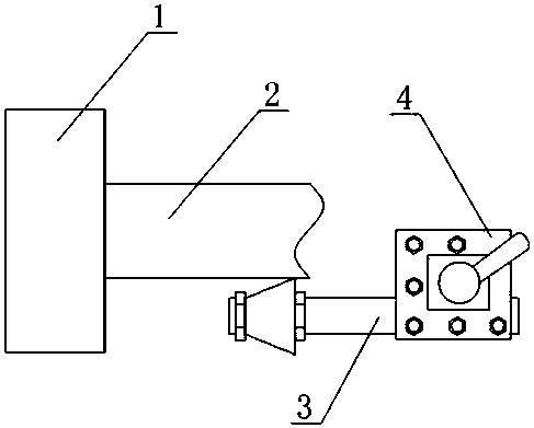
[0023] like Figure 1 to Figure 3 As shown, a lathe workpiece alignment mechanism includes an alignment body 3, the alignment body 3 includes a mounting block 31, an alignment wheel rod 32 and an alignment wheel 35, the installation block 31 is flat, The alignment wheel rod 32 is round rod shape, and one end of the mounting block 31 is fixedly connected with the end of the alignment wheel rod 32, and the length direction of the installation block 31 is parallel to the axial direction of the alignment wheel rod 32, and the alignment wheel 35 is a cone In the form of a platform, the alignment wheel 35 is provided with a through hole along its height direction, and the through hole and the alignment wheel bar 32 form a clearance fit, and the center line of the alignment wheel 35 and the alignment wheel bar 32 is collinear.

[0024] Since the present invention will form a larger interaction force between the mounting block 31 and the knife rest 4 during use, in the present embodim...

Embodiment 2

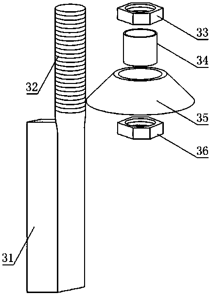
[0026] The present embodiment is further limited on the basis of embodiment 1, as Figure 1 to Figure 3 As shown, it also includes a shaft sleeve 34, an outer limit nut 33 and an inner limit nut 36. The alignment wheel rod 32 is an externally threaded rod, and the shaft sleeve 34 is nested on the alignment wheel rod 32. And the positive and negative deviation of the inner diameter of the shaft sleeve 34 and the outer diameter of the alignment wheel rod 32 is within 0.2 millimeters, the alignment wheel 35 is nested on the shaft sleeve 34, and the alignment wheel 35 forms a gap with the shaft sleeve (34) Cooperate, the inner diameter of the alignment wheel 35 through holes is 0.4-0.8 mm larger than the outer diameter of the axle sleeve 34, the outer limit nut 33 and the inner limit nut 36 are threaded with the alignment wheel rod 32, and the alignment The wheel 35 is located between the outer stop nut 33 and the inner stop nut 36 .

[0027] In the above settings, the alignment ...

Embodiment 3

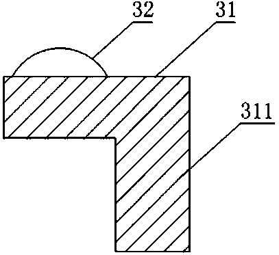
[0029] The present embodiment is further limited on the basis of embodiment 1, as Figure 1 to Figure 3 As shown, since it is very easy to realize that the turning tool mounting surface on the tool rest 4 is parallel to the lathe spindle, in order to make the radial direction of the alignment wheel 35 and the plane where the radial direction of the workpiece 2 are parallel to each other, a plate-shaped stop is also included. The stopper 311 , the limit stopper 311 is fixedly connected to one side of the installation block 31 , and the limit stopper 311 is perpendicular to the installation block 31 . Specifically, a right-angle included angle is formed between the limit block 311 and the mounting block 31. When the present invention is installed on the tool rest 4, the right-angle included angle and the right angle of the turning tool installation station on the tool rest 4 are in good contact with each other. close, that is, it can ensure that the mounting block 31 is parallel...


PUM


Abstract

The invention discloses a workpiece alignment mechanism of a turning lathe. The workpiece alignment mechanism of the turning lathe comprises an alignment part body (3). The alignment part body (3) comprises a mounting block (31), an alignment wheel rod (32) and an alignment wheel (35). The mounting block (31) is in the shape of a flat plate, the alignment wheel rod (32) is in the shape of a round rod, one end of the mounting block (31) is fixedly connected with one end of the alignment wheel rod (32), the length direction of the mounting block (31) is parallel with the axis direction of the alignment wheel rod (32), the alignment wheel (35) is in the shape of a circular truncated cone, a through hole is formed in the alignment wheel (35) in the height direction, the through hole is in clearance fit with the alignment wheel rod (32), and the center line of the alignment wheel (35) and the center line of the alignment wheel rod (32) are in the same line. The workpiece alignment mechanism of the turning lathe has no influence on clamping of a turning tool of the turning lathe, alignment of workpieces can be completed at a time, the coaxiality adjusting quality and efficiency are high, and the workpiece alignment mechanism of the turning lathe can well adapt to various workpieces to be turned.

Description

technical field [0001] The invention relates to the field of lathe processing auxiliary equipment, in particular to a lathe workpiece alignment mechanism. Background technique [0002] A lathe is a machine tool that mainly uses a turning tool to turn a rotating workpiece. It is an indispensable pipeline and equipment processing equipment for the petrochemical industry. [0003] In the prior art, lathes often use chucks to fix parts to be processed. In order to have a good coaxiality between the workpiece and the turning shaft of the lathe to obtain good machining accuracy, the workpiece to be processed is generally pre-clamped on the chuck first, and then the rotation track of the workpiece is observed when the spindle of the lathe rotates at a low speed. If the workpiece has a large swing in the radial direction of the workpiece, it is necessary to adjust the coaxiality between the workpiece and the spindle by re-clamping or tapping the workpiece. The above operations are...

Claims


Application Information

Patent Timeline
IPC IPC(8): B23B25/06
CPCB23B25/06
Inventor 贺昶明
Owner CHENGDU ZHIRONG ZHICHUANG INTPROP MANAGEMENT CO LTD
Why Eureka
Try Eureka