Welding rotatable work fixture for automobile front bumper beam sub assembly

A tooling fixture and front buffer technology, which is applied in the field of rotatable tooling fixtures for welding of automobile front buffer beam sub-assemblies, can solve problems such as affecting production efficiency, high labor intensity, and increasing labor intensity of operators, so as to improve welding processing efficiency, The effect of reducing labor intensity and excellent product quality

Inactive Publication Date: 2014-05-21
JIANGSU CHANGTONG VEHICLE DEV
View PDF6 Cites 17 Cited by
  • Summary
  • Abstract
  • Description
  • Claims
  • Application Information

AI Technical Summary

Problems solved by technology

[0002] The connection of each part of the front bumper beam sub-assembly of the automobile is completed by welding. At present, the widely used welding tooling mainly has the following problems: 1. The pressing work mainly depends on the operator, and the operator installs the large workpiece on the tooling Finally, manually compress the workpiece, which is time-consuming and labor-intensive, and it is difficult to ensure the accuracy and quality of the product; 2. When manually welding the front bumper beam sub-assembly, due to the difference in welding position and angle The difference is that the welding cannot be completed at one time, and it is necessary to stop and go to the back of the workpiece to complete the remaining part of the welding, which will also cause a waste of welding time, greatly affect the production efficiency, and increase the labor intensity of the operator; 3. The fixed position of the positioning structure cannot be carried out Adjustment, it is impossible to avoid the phenomenon that the parts cannot be installed and the size of the parts after welding is out of tolerance due to the manufacturing error of each batch of parts; 4. After the welding work is completed, the workpiece needs to be removed by personnel from the positioning pin and positioning block on the tooling. The workpiece can be taken out, and the production efficiency is low

Method used


Image

  • Welding rotatable work fixture for automobile front bumper beam sub assembly
  • Welding rotatable work fixture for automobile front bumper beam sub assembly
  • Welding rotatable work fixture for automobile front bumper beam sub assembly

Examples


Embodiment Construction

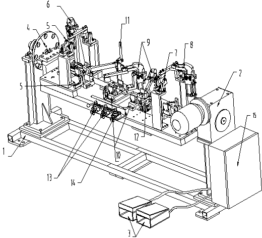
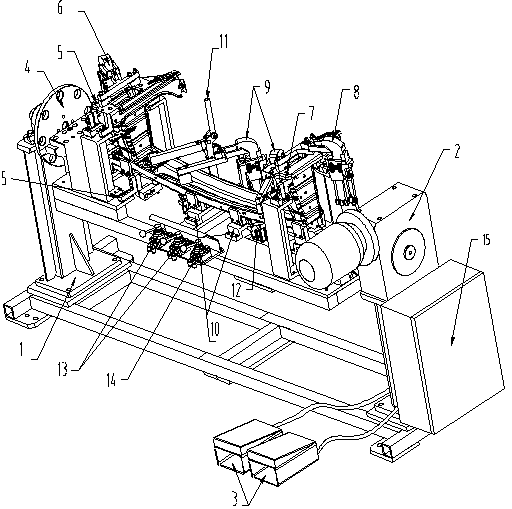
[0015] Depend on figure 1 , figure 2 It is known that a welding rotatable fixture of the front buffer beam subassembly of an automobile is composed of a base 1, a flipping motor 2, a foot switch 3, a flipping floor assembly 4, a six-way adjustment main positioning mechanism 5, and a left side compression cylinder mechanism 6. Six-direction adjustment auxiliary positioning mechanism machine 7. Right side compression cylinder mechanism 8. Front compression cylinder mechanism 9. Assembly six-direction adjustment positioning mechanism 10. Compression hand pliers 11. Supporting cylinder mechanism 12. Compression cylinder The control valve 13, the supporting cylinder control valve 14, and the reduction box 15 are composed; the turning motor 2 and the reducing box 15 are installed on the right side of the base 1, and the turning bottom plate assembly 4 is installed on the left side, and the turning bottom plate assembly 4 and the turning motor 2 pass through Bolts are fixedly conne...


PUM


Abstract

A welding rotatable work fixture for an automobile front bumper beam sub assembly comprises a base (1). The right side of the base (1) is provided with a tilt motor (2) and a speed reducing case (15), and the left side of the base (1) is provided with a turnover board assembly (4). The welding rotatable work fixture is characterized in that a six-directional adjusting main positioning mechanism (5), a left side face compression air cylinder mechanism (6), a six-directional adjusting auxiliary positioning mechanism (7), a right side face compression air cylinder mechanism (8), a front face compression air cylinder mechanism (9), compression pliers (11) and a material supporting air cylinder mechanism (12) are inflated with air and tightly press the automobile front bumper beam sub assembly, a foot switch (3) controls the tilt motor (2) to rotate, the turnover board assembly (4) rotates by 0-270 degrees according to the welding position, and the welding position is carried out. By means of the welding rotatable work fixture, the machining efficiency can be improved manyfold, the speed is high, the benefits are high, the labor intensity is reduced, and the quality of machined products is good.

Description

technical field [0001] The invention relates to a welding process of an automobile parts assembly, in particular to a rotatable fixture for welding a front buffer beam subassembly of an automobile. Background technique [0002] The connection of each part of the front bumper beam sub-assembly of the automobile is completed by welding. At present, the widely used welding tooling mainly has the following problems: 1. The pressing work mainly depends on the operator, and the operator installs the large workpiece on the tooling Finally, manually compress the workpiece, which is time-consuming and labor-intensive, and it is difficult to ensure the accuracy and quality of the product; 2. When manually welding the front bumper beam sub-assembly, due to the difference in welding position and angle The difference is that the welding cannot be completed at one time, and it is necessary to stop and go to the back of the workpiece to complete the remaining part of the welding, which wil...

Claims


Application Information

Patent Timeline
Patent Type & Authority Applications(China)
IPC IPC(8): B23K37/04
CPCB23K37/0443B23K37/047
Inventor 李德兴曾庆国
Owner JIANGSU CHANGTONG VEHICLE DEV
Why Eureka
Try Eureka