
Automobile exhaust connecting pipe welding, clamping, fixing and displacing tool

A technology for automobile exhaust and connecting pipes, which is applied in welding equipment, auxiliary welding equipment, welding/cutting auxiliary equipment, etc. Efficiency and quality, the effect of ensuring docking accuracy

Active Publication Date: 2020-09-04
徐州凯密斯科技有限公司
View PDF6 Cites 1 Cited by
  • Summary
  • Abstract
  • Description
  • Claims
  • Application Information

AI Technical Summary

Problems solved by technology

[0002] The automobile is a product of modern industry. The invention of the automobile has accelerated the development of modern civilization and improved people's living standards. In automobile production, it is necessary to weld the exhaust pipe of the automobile, and the exhaust pipe of the automobile is generally bent. Yes, during welding, it is necessary to manually adjust the position and fix it before welding. This method is very inconvenient and not conducive to batch processing, and manual adjustment cannot guarantee the accuracy of the welding position, which affects the automobile row. Yield rate of gas connecting pipe
[0003] However, the general tooling fixture cannot adjust the position according to the needs of welding when clamping the automobile exhaust connecting pipe with a curved structure. Usually, it is necessary to readjust the fixture to adjust the position of the automobile exhaust connecting pipe. The welding process of the exhaust connecting pipe has brought inconvenience

Method used


Image

  • Automobile exhaust connecting pipe welding, clamping, fixing and displacing tool
  • Automobile exhaust connecting pipe welding, clamping, fixing and displacing tool
  • Automobile exhaust connecting pipe welding, clamping, fixing and displacing tool

Examples


Embodiment Construction

[0023] In order to make the technical means, creative features, goals and effects achieved by the present invention easy to understand, the present invention will be further described below in conjunction with specific illustrations. It should be noted that, in the case of no conflict, the embodiments in the present application and the features in the embodiments can be combined with each other.

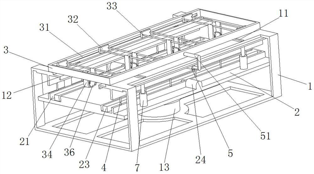
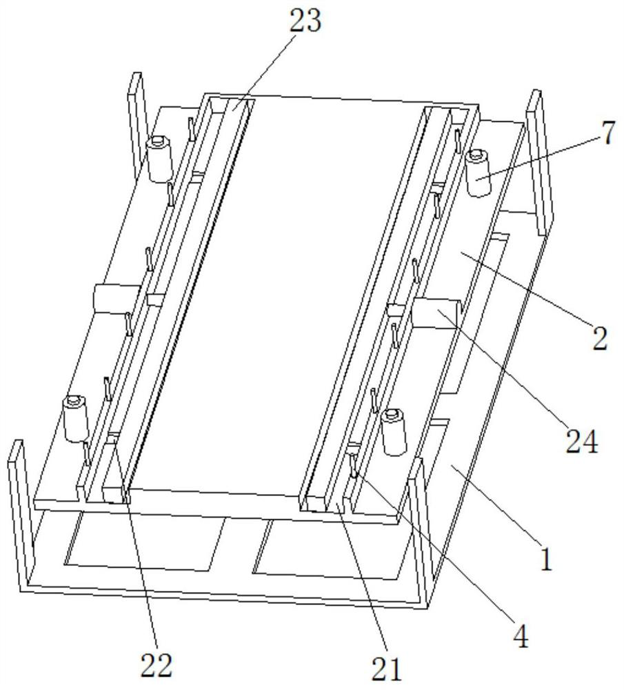
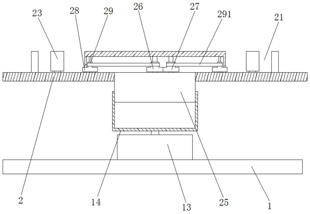
[0024] Such as Figure 1 to Figure 5 As shown, a welding and clamping fixed displacement tool for an automobile exhaust connecting pipe includes a fixed machine tool 1, a lifting table 2 is inserted in the fixed machine tool 1, and a number of spring telescopic rods 7 are symmetrically and fixedly connected to the lifting table 2, and the spring telescopic The top of the rod 7 is fixedly connected to the fixed machine tool 1, and the top of the fixed machine tool 1 is symmetrically provided with a No. 1 chute 11. The top of the fixed machine tool 1 is provided with a movable frame 3,...


PUM


Abstract

The invention relates to the field of auto spare parts processing, in particular to an automobile exhaust connecting pipe welding, clamping, fixing and displacing tool which comprises a fixed machinetool; a lifting table is inserted in the fixed machine tool; a plurality of spring telescopic rods are symmetrically and fixedly connected onto the lifting table; first sliding chutes are symmetrically formed in the top of the fixed machine tool; a movable frame is arranged on the top of the fixed machine tool; the bottom of the movable frame is inserted in the first sliding chutes; fixed groovesare symmetrically formed in the lifting table; clamping grooves are symmetrically formed above the fixed grooves in the fixed machine tool; second sliding chutes are symmetrically formed in the fixedgrooves; adjusting clamping strips are arranged in the fixed grooves; a first hydraulic cylinder is symmetrically and fixedly connected with the two sides of the lifting table; and the output end of the first hydraulic cylinder penetrates through the fixed grooves to be fixedly connected with one side of the adjusting clamping strips. The automobile exhaust connecting pipe welding, clamping, fixing and displacing tool is simple in structure, can simultaneously clamp and fix a plurality of exhaust connecting pipes precisely, ensures welding precision and is suitable for popularization.

Description

technical field [0001] The invention relates to the field of auto parts processing, in particular to a welding, clamping, fixing, and displacement tool for an automobile exhaust connecting pipe. Background technique [0002] The automobile is a product of modern industry. The invention of the automobile has accelerated the development of modern civilization and improved people's living standards. In automobile production, it is necessary to weld the exhaust pipe of the automobile, and the exhaust pipe of the automobile is generally bent. Yes, during welding, it is necessary to manually adjust the position and fix it before welding. This method is very inconvenient and not conducive to batch processing, and manual adjustment cannot guarantee the accuracy of the welding position, which affects the automobile row. The yield rate of gas connecting pipes. [0003] However, the general tooling fixture cannot adjust the position according to the needs of welding when clamping the ...

Claims


Application Information

Patent Timeline
Patent Type & Authority Applications(China)
IPC IPC(8): B23K37/047
CPCB23K37/047
Inventor 刘勇
Owner 徐州凯密斯科技有限公司
Learn More