
Plug-in-type column pile

A plug-in, post-piling technology, applied in the field of post-piling, can solve the problems of poor site utilization, inability to produce specifications, and quantity adjustment and storage position, and achieve reliable post-piling, simple coaxial plug-in structure, and stable quantity. Effect

Inactive Publication Date: 2014-05-21
江苏纳特管业有限公司
View PDF0 Cites 0 Cited by
  • Summary
  • Abstract
  • Description
  • Claims
  • Application Information

AI Technical Summary

Problems solved by technology

It is not suitable to use piles for temporary storage in the production workshop, because the location of the piles is fixed, and the storage location cannot be adjusted according to the production specifications and quantities, resulting in poor site utilization and other problems

Method used


Image

  • Plug-in-type column pile

Examples


Embodiment 1

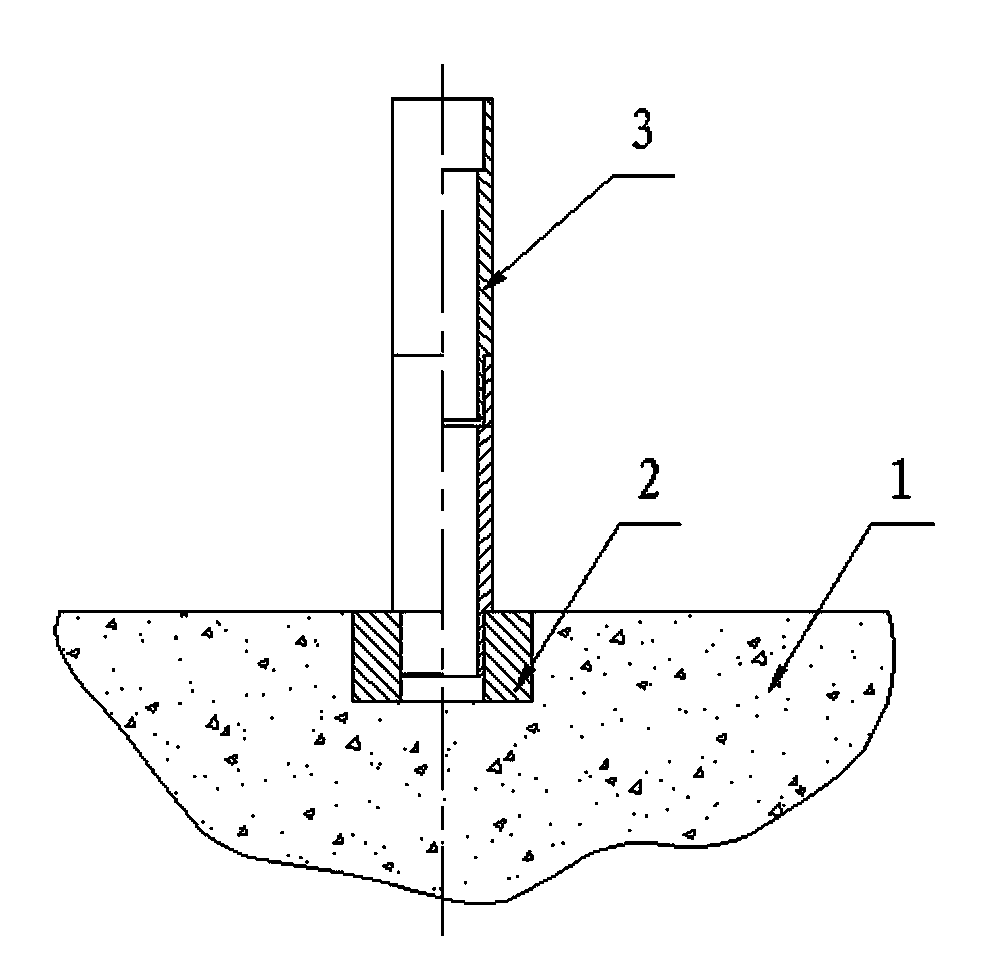
[0015] This embodiment is used to stack 5 layers of DN600mm polyethylene pipes. Because the diameter of the pipe is relatively thick, the height of the stack is high, and the weight is heavy, it is selected to use 6 pillars 3 to be plugged into one body, and each pillar 3 is 50mm long. , outer diameter Φ100mm, interface and joint diameter Φ90mm. In order to ensure that each post 3 is inserted in place, the depth of the inner hole of the casing 2 and the depth of the interface of the post 3 are made to be 150 mm, and the joint length of the matching post 3 is 140 mm. Under this size condition, the inserted column pile 3 forms a pile and is positioned in the casing 2, which is mechanically connected, and the limit is reliable, which fully meets the limit requirements for stacking 5-layer pipes. In addition to simple structure and easy plugging, the present invention has greater flexibility. When the production workshop needs to adjust the temporary stacking place of products, th...

Embodiment 2

[0017] In this embodiment, the DN100mm polyethylene pipe used for stacking is relatively small in diameter and light in weight, so the requirements for the strength of the pile 3 are also small, so the pile 3 with an outer diameter of Φ50mm can meet the normal pile requirements. High limit requirements. The rest of the structure of the pile 3 is the same as that of Example 1, the main size changes are that the total length is changed to 300mm, the inner diameter of the upper end joint and the outer diameter of the lower end joint are equal to Ф40mm, the depth of the inner hole of the casing 2 and the joint depth of the pile 3 are 100mm , the joint length of the column pile 3 is 90mm. The application effect of this embodiment is similar to that of Embodiment 1.

[0018] In addition to being applied in polyethylene pipe production lines, the present invention can also be used for on-site stacking of products in production lines such as steel pipes, copper pipes, and aluminum pi...


PUM


Abstract

The invention discloses a plug-in-type column pile, which is jointly formed by a casing which is embedded in a concrete ground and a column pile which is plugged in the casing in a positioned way. The inner hole of the casing is upward and the top end surface of the casing and the concrete ground are at the same level. The column pile is a shoulder-type hollow shaft component with the length of 300-500mm and the outer diameter Phi of 50-100mm, a circular hole socket is formed in the upper end of the column pile, a columnar plug is arranged at the lower end of the column pile and the outer diameter of the plug is equal to the diameter of the socket and the inner hole of the casing. One to six column piles are coaxially plugged, wherein the plug of the first column pile is directly plugged in the inner hole of the casing and is connected in the positioned way and the follow-up column piles are connected through clearance fit of the sockets and the plugs. The plug-in-type column pile has the advantages that since the plug-in structure is adopted, the limiting reliability is high, the normal staking height limiting requirement of pipe products is fully met and the plug-in-type column pile is particularly suitable for being used as a limiting pile for pipe product stacking on the site of the production line.

Description

technical field [0001] The invention relates to a column pile, in particular, the invention relates to a plug-in type column pile. Background technique [0002] The pipe industry usually adopts the method of laying flat and building high to store products. The natural characteristics of round pipes are easy to roll, and the stability of multi-layer stacking is poor. In order to improve the stability of the circular pipe stack, the traditional structure inserts wedges on both sides of the bottom pipe or places piles on both sides of the pipe to limit the position. Although these two conventional limiting structures are simple, they can both improve the stability of the tube stack. However, there are still deficiencies in the traditional structure, which cannot meet the actual needs. For example, the wedges only rely on friction to limit the position of the round tubes on both sides of the bottom layer, and one round tube is reduced for each layer, and the final stack of tub...

Claims


Application Information

Patent Timeline
Patent Type & Authority Applications(China)
IPC IPC(8): B65G1/14
Inventor 张亚林
Owner 江苏纳特管业有限公司
Learn More