Lifting device of drainage pipeline of toilet bowl

A technology for drainage pipes and toilets, which is applied to water supply devices, flushing toilets, and flushing equipment with water tanks, etc. It can solve the problems that are prone to failure, the U-shaped water storage section cannot be formed, and the middle section of the drainage hose cannot be raised, etc. question

Inactive Publication Date: 2014-05-21
李建飞
View PDF0 Cites 3 Cited by
  • Summary
  • Abstract
  • Description
  • Claims
  • Application Information

AI Technical Summary

Problems solved by technology

[0004] However, the control device that can control the forward and reverse rotation of the motor has a complex circuit structure and is prone to failure, so it is not suitable for various occasions that have high requirements for cost and reliability, such as homes and public places.
Furthermore, once the drive mechanism puts down the middle section of the drain hose, there will be a sudden power failure, and the middle section of the drain hose will not be able to be raised, so that the U-shaped water storage section cannot be formed, and the odor in the ground sewage pipe mouth will pass through the drain hose and the drain hose. Potty spilled into bathroom

Method used


Image

  • Lifting device of drainage pipeline of toilet bowl
  • Lifting device of drainage pipeline of toilet bowl
  • Lifting device of drainage pipeline of toilet bowl

Examples


Embodiment 1

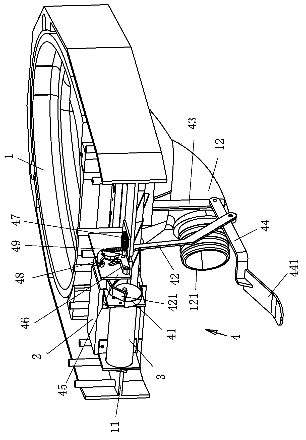
[0023] For the three-dimensional structure of an embodiment of the toilet drainage pipe lifting device of the present invention installed on the toilet main body, please refer to figure 1 . The bedpan 1 of the elevating toilet is installed on a frame 11 that can be raised and lowered, and the rear upper part of the frame 11 is equipped with a control device 2, an electric motor 3 and a transmission mechanism 4 of the drainage pipe lifting device. Control device 2 coordinates the water inlet solenoid valve ( figure 1 (not shown) and the action of the motor 3 in the hoisting device.

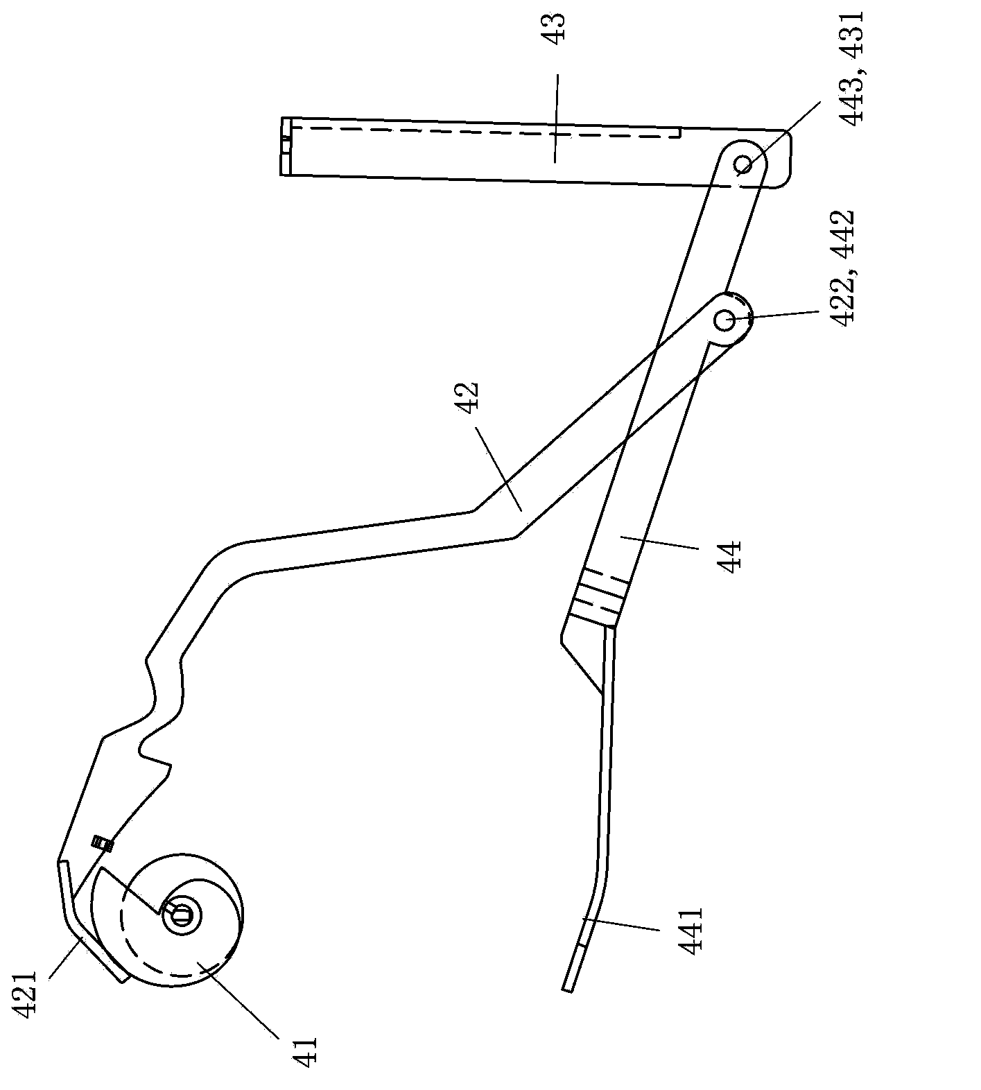
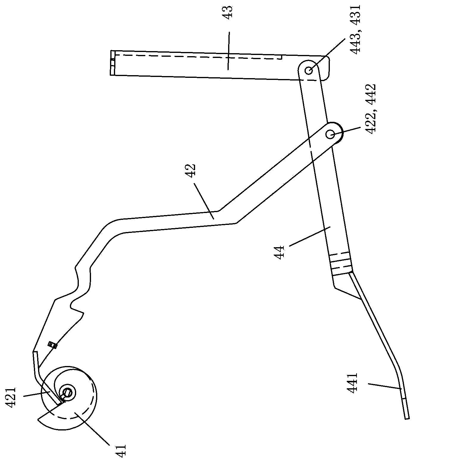
[0024] The main structure of the transmission mechanism 4 includes a cam 41 , a moving rod 42 , a fixed rod 43 and a swing rod 44 . The cam 41 is mounted on the rotating shaft of the motor 3, and the lowest point of the outer circumference of the cam 41 reaches the highest point of its outer circumference through an extended plane. The upper end of the fixed rod 43 is fixed to the rear and lower...


PUM


Abstract

The invention discloses a lifting device of a drainage pipeline of a toilet bowl, and relates to a lifting device of a drainage flexible pipeline of a lifting type toilet bowl. The lifting device of the drainage pipeline of the toilet bowl is provided with a motor and a transmission mechanism, wherein the motor is installed at the upper rear portion of a toilet bowl framework; the transmission mechanism is installed in the middle section of the lifting drainage flexible pipeline and comprises a cam, an oscillating bar and a movable bar; the cam is installed on a rotary shaft of the motor; the lowest point of the periphery of the cam passes through an extensional plane and reaches the highest point of the periphery of the cam; the oscillating bar is arranged below the middle section of the drainage flexible pipeline, the front end of the oscillating bar is hinged to the lower rear portion of the toilet bowl framework, and the rear end of the oscillating bar supports the middle section of the drainage flexible pipeline; the movable bar is arranged between the cam and the oscillating bar aslant, the upper end of the movable bar is provided with a pressing tongue abutting against the periphery of the cam, and the lower end of the movable bar is hinged to the front section of the oscillating bar. The motor only needs to rotate in one direction, then the transmission mechanism of the lifting device can achieve operation of putting down and lifting the middle section of the drainage flexible pipeline according to the requirements of a control device, and therefore the circuit structure of the control device is simplified, the cost is lowered, and reliability is improved.

Description

technical field [0001] The invention relates to a lifting device for a drainage hose of a lift-type toilet. Background technique [0002] The lift toilet adopts a U-shaped drain hose that can be lifted in the middle section to guide the sewage in the bedpan sewage pipe to the sewage outlet on the ground. When the lifting device lowers the middle section of the drainage hose, the middle section of the drainage hose is higher than the sewage pipe opening on the ground and lower than the nozzle opening of the bedpan sewage pipe, and the sewage in the bedpan can smoothly flow to the sewage pipe opening on the ground. When the lifting device lifts the middle section of the drainage hose, the middle section of the drainage hose is higher than the sewage outlet on the ground and higher than the mouth of the bedpan sewage pipe, and forms a section between the middle section of the drainage hose and the mouth of the bedpan sewage pipe Small U-shaped water storage section; the clean ...

Claims


Application Information

Patent Timeline
Patent Type & Authority Applications(China)
IPC IPC(8): E03D5/10E03D11/18
Inventor 李建飞
Owner 李建飞
Why Eureka
Try Eureka