Hydraulic telescopic device for elevator shaft mold and operating method thereof

A hydraulic telescopic and elevator shaft technology, which is applied in the treatment of formwork, formwork/template/work frame, and on-site preparation of building components, can solve the problems of time-consuming, excessive structural stress, and high cost, and achieves The effect of requiring low quality, small safety risk and simple operation

Active Publication Date: 2014-05-21
CHINA MCC5 GROUP CORP
View PDF7 Cites 13 Cited by
  • Summary
  • Abstract
  • Description
  • Claims
  • Application Information

AI Technical Summary

Problems solved by technology

But there are still some deficiencies, such as: the cylinder formwork uses the four-column cantilever climbing frame as the fulcrum to climb, not only the structure is redundant, but the key is that the four cantilever columns are set, which makes transportation and installation inconvenient. This technology is restricted; in addition, there is a lack of simple and effective measures for the installation and connection structure of the cylinder mold and the power

Method used


Image

  • Hydraulic telescopic device for elevator shaft mold and operating method thereof
  • Hydraulic telescopic device for elevator shaft mold and operating method thereof
  • Hydraulic telescopic device for elevator shaft mold and operating method thereof

Examples


Embodiment 1

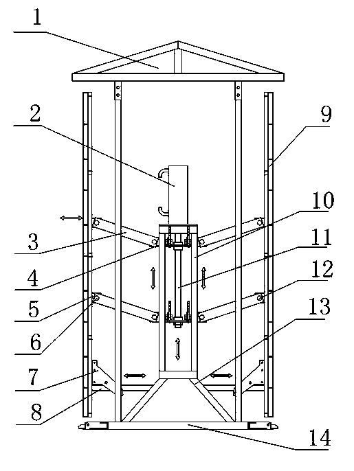
[0025] Such as figure 1 , figure 2 As shown, the hydraulic expansion device for the shaft mold of the elevator shaft includes a cylinder mold connected in turn by several telescopic templates 9, and several angle molds are arranged between adjacent telescopic templates 9 in the telescopic template 9; The cylinder mold is provided with a hydraulic rod 2 and a bracket 10 inside, the hydraulic rod 2 is installed on the upper end of the bracket 10, a transmission screw 11 is arranged in the bracket 10, and the transmission screw 11 is connected with the hydraulic rod 2, and the outer wall of the transmission screw 11 is set There are two groups of linkage mechanisms, and the two ends of the linkage mechanisms are respectively connected with the transmission screw 11 and the corresponding telescopic formwork 9 . Telescopic formwork 9 adopts steel formwork, the plane size of steel formwork is 2.2m*2.2m, and the elevator shaft is generally a regular square shape, so four steel form...

Embodiment 2

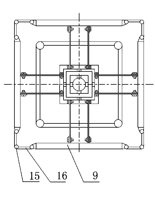
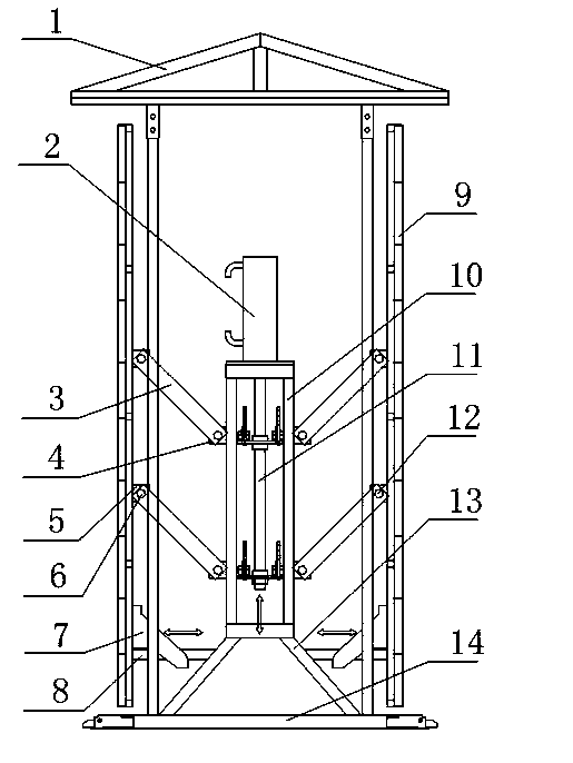
[0035] like image 3 , Figure 4 As shown, when the concrete reaches the demoulding strength, the hydraulic pump starts, the hydraulic rod 2 descends, and drives the transmission screw 11 to descend, the horizontal pulley frame 7 and the synchronous adjustment connecting rod 3 shrink inward, the horizontal telescopic beam 5 moves inward, and the telescopic formwork is pulled toward the Move and release the mold from inside to realize that the horizontal telescopic beam 5, the synchronous adjustment connecting rod 3 and the fixed rod 4 are not on the same straight line, so that the fixed rod 4 is below the corresponding horizontal telescopic beam 5, and the corner mold is in a contracted state at the same time, and the same corner mold The included angle between the two hinges 16 inside is an acute angle, and the smaller the angle, the more obvious the demoulding effect.

[0036] During the demoulding process, the bracket 10 is fixed, the hydraulic pump is activated, and the h...


PUM


Abstract

The invention discloses a hydraulic telescopic device for an elevator shaft mold. The hydraulic telescopic device comprises the shaft mold formed by several telescopic templates into a circle, wherein several angle molds are arranged between adjacent telescopic templates in the telescopic templates, a hydraulic rod and a support are arranged in the shaft mold, a drive screw is arranged in the support, and the two ends of a connecting rod mechanism set are connected with the drive screw and the corresponding telescopic templates respectively. The hydraulic rod lifts and drives the drive screw to lift, horizontal pulley frames and synchronization regulation connecting rods extend outwards, horizontal telescopic beams move outwards, the telescopic templates are pushed to move outwards in position, and the situation that the horizontal telescopic beams, the synchronization regulation connecting rods and fixing rods are on the same straight line is achieved. At the moment, the hydraulic telescopic device is in the maximum telescopic state. The hydraulic telescopic device and the operating method of the hydraulic telescopic device are not high in cost, the hydraulic telescopic device is automatically machined and can be repeatedly used, operations can be completed by one person, the requirement for quality of operation staff is not high, and the hydraulic telescopic device is easy to operate, is automatically controlled by a hydraulic system and is low in safety dangerousness.

Description

technical field [0001] The invention relates to a hydraulic telescopic device for an elevator shaft mold and an operating method thereof, and belongs to the field of mold drafting after pouring of an elevator shaft. Background technique [0002] The elevator shaft is the shaft where the elevator is installed. The size of the elevator shaft is determined according to the selection of the elevator. The elevator track and the counterweight track are installed on the shaft wall, and the elevator door is installed in the reserved door opening. There is an elevator machine room on the top of the shaft. Building shaft / elevator shaft climbing formwork, as a category of building formwork, has been embodied in building climbing formwork technology. With the continuous update of high-rise building construction technology, the traditional vertical shaft mold technology has become the bottleneck of high-rise building rapid construction technology. Recently, the tool-type self-climbing mo...

Claims


Application Information

Patent Timeline
IPC IPC(8): E04G11/28E04G19/00E04G21/00
Inventor 谭启厚吕兴建
Owner CHINA MCC5 GROUP CORP
Why Eureka
Try Eureka