
Sound wave remote measuring sound insulator following drilling

A technology of sound insulation and sound wave, which is applied in the directions of measurement, earthwork drilling and production, wellbore/well components, etc., and can solve problems such as interference of sound wave signal transmission while drilling

Inactive Publication Date: 2014-05-21
XI'AN PETROLEUM UNIVERSITY
View PDF8 Cites 0 Cited by
  • Summary
  • Abstract
  • Description
  • Claims
  • Application Information

AI Technical Summary

Problems solved by technology

In comparison, the noise generated by the drill tool assembly and the drill bit during the drilling process is uploaded to the acoustic wave transmission channel while drilling, which interferes with the transmission of the acoustic wave signal while drilling

Method used


Image

  • Sound wave remote measuring sound insulator following drilling
  • Sound wave remote measuring sound insulator following drilling
  • Sound wave remote measuring sound insulator following drilling

Examples


Embodiment Construction

[0019] The present invention will be described in detail below in conjunction with the accompanying drawings.

[0020] refer to figure 1 , a sound insulator for sound wave telemetry while drilling, comprising a first hollow cylindrical rod 1, a second hollow cylindrical rod 3, a third hollow cylindrical rod 4, a fourth hollow cylindrical rod 5, a fifth hollow cylindrical rod 7 and a first conical Rod 2, second conical rod 6, the left end of the first hollow cylindrical rod 1 is the input end interface of the sound insulation body, the right end of the first hollow cylindrical rod 1 is connected with the big end of the first conical rod 2, the first conical rod 2 The small end of the small end is connected with an end of the second hollow cylindrical rod 3, the other end of the second hollow cylindrical rod 3 is connected with an end of the third hollow cylindrical rod 4, and the other end of the third hollow cylindrical rod 4 is connected with the fourth hollow cylindrical rod...


PUM


Abstract

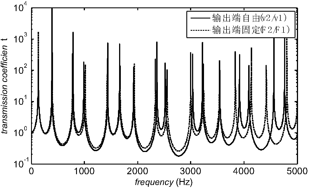
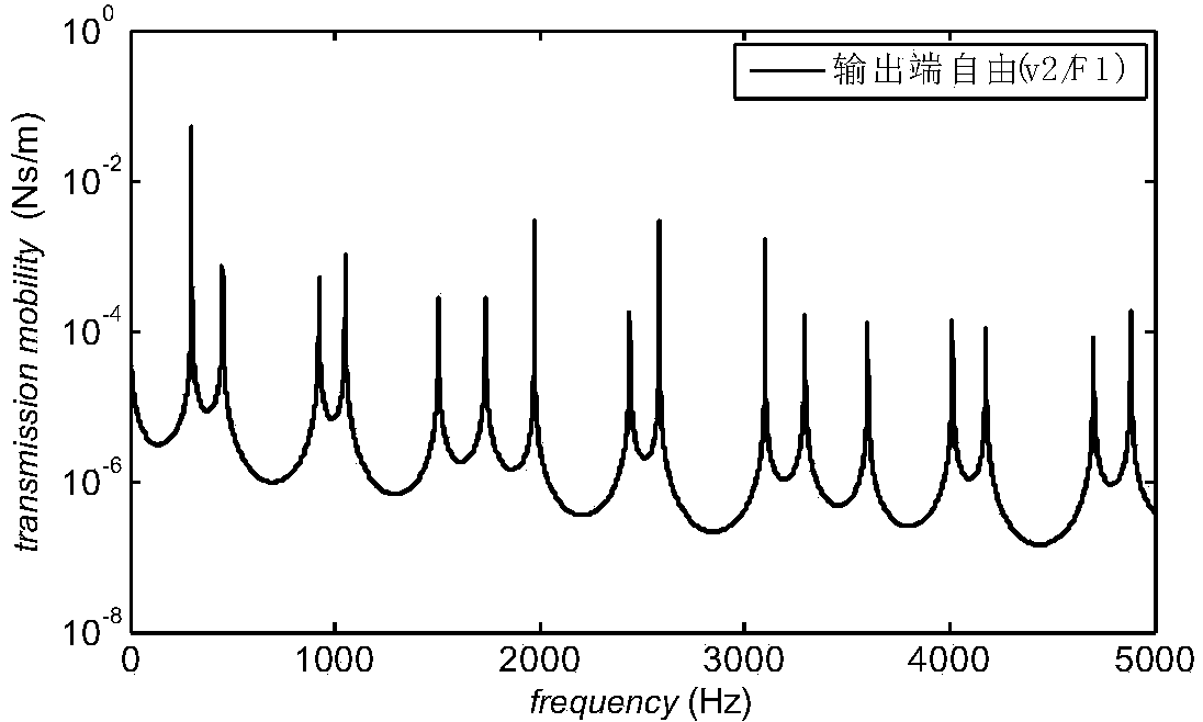
A sound wave remote measuring sound insulator following drilling is formed by connecting five hollow cylindrical rods with different cross sections and two conical rods, an input end connector and an output end connector of the sound insulator are both NC 50 standard threaded connectors, the length of the whole sound insulator is 8686.8 mm, and the largest cross section radius of the sound insulator is 89 mm and is kept consistent with the length of a standard drill rod. On the basis of the longitudinal wave vibration transmission theory and through transmission and reflection of sound waves passing through the hollow cylindrical rods with different cross sections, sound wave signals within a certain frequency range can be made to generate large attenuation, the parts, with the cross sections gradually changing, of the conical rods have the stress dispersion effect, mechanical strength of a connection and transition segment of a drilling column is guaranteed, meanwhile, sound transmission loss of the sound insulator is obtained in a combined mode, the attenuation band frequency domain of the sound insulator is obtained, suppression of drill collar mode waves excited by a monopole sound source on stratum longitudinal waves excited by a transmitting transducer is eliminated, and technological support is provided for application of sound wave remote measuring following drilling to underground engineering.

Description

technical field [0001] The invention relates to the technical field of acoustic wave telemetry while drilling, in particular to a sound insulation body for acoustic wave telemetry while drilling. Background technique [0002] Acoustic telemetry while drilling has achieved good results in production wells, but in the process of oil drilling, research still needs to be done. In comparison, the noise generated by the drill tool assembly and the drill bit during the drilling process is uploaded to the acoustic wave transmission channel while drilling, which interferes with the transmission of the acoustic wave signal while drilling. [0003] The acoustic wave telemetry instrument while drilling is mainly composed of acoustic wave transmitting transducer, receiving transducer, sound insulation body and supporting electronic circuit and other parts. When the acoustic wave signal generated by the acoustic wave transmitting transducer propagates along the drill pipe to the ground, ...

Claims


Application Information

Patent Timeline
IPC IPC(8): E21B47/14
Inventor 谢海明周静张峰尚海燕燕并南刘选朝
Owner XI'AN PETROLEUM UNIVERSITY
Learn More