
Engine cooling system

An engine cooling and engine block technology, applied in the direction of engine cooling, engine components, machine/engine, etc., can solve the problems of poor lubrication effect, waste of energy efficiency, low temperature of gearbox gear oil, etc., to avoid the temperature of gearbox gear oil. too low effect

Active Publication Date: 2014-05-21
ANHUI JIANGHUAI AUTOMOBILE GRP CORP LTD
View PDF5 Cites 52 Cited by
  • Summary
  • Abstract
  • Description
  • Claims
  • Application Information

AI Technical Summary

Problems solved by technology

[0003] For the above two connection forms of the engine cooling system, the DCT cooler is always in a long-pass state, so that when the engine is cold started in winter, the above two connection forms will cause the coolant temperature in the system to be low, and the DCT cooling The gearbox is always in the working state, that is, the transmission gear oil is always in the state of heat dissipation, which directly leads to the temperature of the transmission gear oil being too low, the lubrication effect is poor, and it will also cause problems such as increased fuel consumption and waste of energy efficiency.

Method used


Image

  • Engine cooling system
  • Engine cooling system
  • Engine cooling system

Examples


Embodiment Construction

[0058] Embodiments of the present invention are described in detail below, examples of which are shown in the drawings, wherein the same or similar reference numerals designate the same or similar elements or elements having the same or similar functions throughout. The embodiments described below by referring to the figures are exemplary only for explaining the present invention and should not be construed as limiting the present invention.

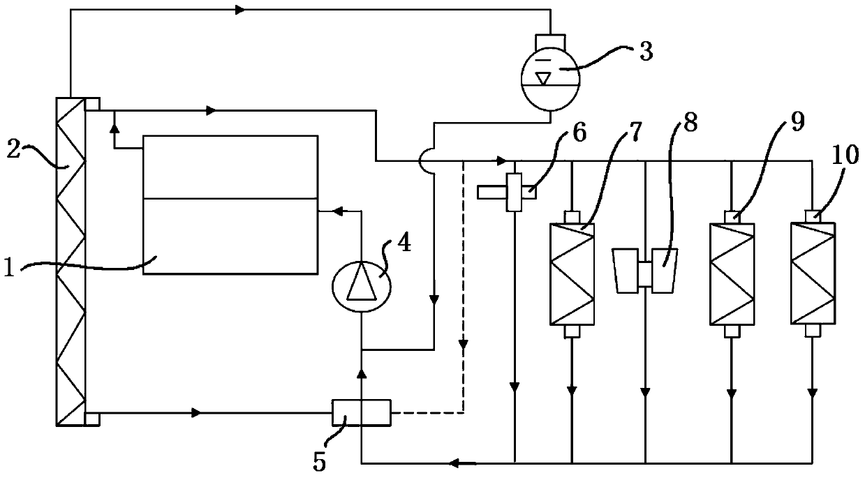
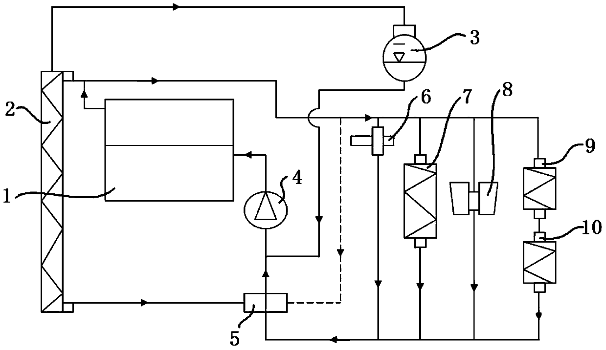
[0059] refer to figure 1 with figure 2 , respectively show the structural diagrams of the traditional parallel and series engine cooling systems, the difference between these two engine cooling systems is only the connection mode of the heater 9 and the gearbox cooler 10, both of these two engine cooling systems include cooling The liquid pump 4, the water jacket arranged in the cylinder block and cylinder head of the engine 1, the first thermostat 5, the radiator 2 and the gearbox cooler 10. Wherein, the circulation circuit of the co...


PUM


Abstract

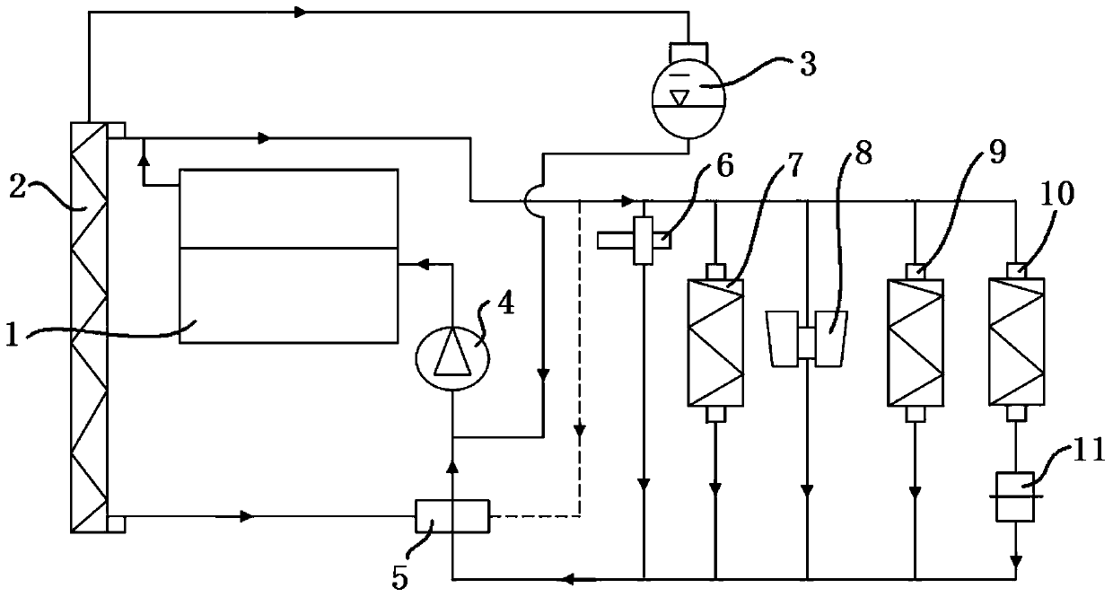
The invention discloses an engine cooling system which comprises a coolant pump, an engine water jacket, a first thermostat, a radiator, and a transmission cooler, wherein a circulation loop of a coolant in the coolant pump comprises a large circulation loop going through the water jacket, the thermostat and the radiator and a small circulation loop going through the water jacket and the thermostat, the transmission cooler is connected in parallel with the small circulation loop, the first thermostat is provided with a main valve whose opening changes along with the change of the temperature of the coolant and an auxiliary valve whose opening changes along with the change of the temperature of the coolant, the main valve of the first thermostat is connected with the radiator to control the coolant flow in the large circulation loop, the auxiliary valve of the first thermostat is connected with the coolant pump to control the coolant flow in the small circulation loop, the engine cooling system further comprises a second thermostat, the second thermostat is connected in series with the transmission cooler to control the coolant flow passing by the transmission cooler, and a branch comprising the transmission cooler and the second thermostat is connected in parallel with the small circulation loop.

Description

technical field [0001] The invention relates to the technical field of engine cooling, in particular to an engine cooling system. Background technique [0002] At present, the engine cooling system of a passenger car equipped with a dual-clutch automatic transmission (DCT, Dual Clutch Transmission) is mostly connected to the engine in a series / parallel manner. figure 1 , shows a schematic structural diagram of a traditional parallel engine cooling system. The traditional parallel engine cooling system includes a radiator 2, a coolant pump 4, a first thermostat 5, a throttle valve 6, an expansion tank 3, an oil cooling 7, turbocharger 8, heater 9, gearbox cooler 10 (especially DCT cooler) and water circuit, wherein the heater 9 and gearbox cooler 10 are connected in parallel, the first thermostat 5 Installed on the liquid inlet side of the waterway. refer to figure 2 , shows a schematic structural diagram of a traditional serial engine cooling system, the traditional seri...

Claims


Application Information

Patent Timeline
IPC IPC(8): F01P7/16
Inventor 翟晓红翁锐
Owner ANHUI JIANGHUAI AUTOMOBILE GRP CORP LTD
Learn More