
Straight-through type narrow-pipe wind collecting wind power generation system

A wind power generation system, straight-through technology, applied to wind power generator components, wind power engines, wind power generators at right angles to the wind direction, etc., can solve the problem of affecting wind energy utilization and power generation efficiency, reducing pressure and wind speed, reducing air pressure difference, etc. problems, to achieve the effect of improving wind energy utilization and power generation efficiency, increasing the degree of shrinkage, and increasing the sweeping area

Active Publication Date: 2014-05-21
无锡金蝎中蕴风电科技有限公司
View PDF7 Cites 22 Cited by
  • Summary
  • Abstract
  • Description
  • Claims
  • Application Information

AI Technical Summary

Problems solved by technology

The current wind gathering type wind power generation device usually sets the air inlet as a converging narrow tube to increase the wind speed. Since the wind is the result of air flow due to the pressure difference between different positions, the wind flows in the narrow tube. During the process, the flow rate will be affected by the resistance of the inner wall of the pipeline and the internal pressure, and the wind speed increase is actually very limited. For wind power generation devices, since the pressure inside the pipe gradually increases with the accumulation of air, the pressure difference of the air between the pipe inlet and the inside of the pipe decreases, which will hinder the further entry of the airflow, and finally hinder the further increase of the wind speed
In order to effectively increase the wind speed in the narrow tube and further improve the utilization rate of wind energy, the applicant conducted innovative research on the basis of a single narrow tube, and created a double-duct wind gathering wind power system consisting of two narrow tubes connected in front and behind. The power generation device, specifically, the auxiliary narrow pipe is socketed outside the main narrow pipe, there is an axial distance between the air inlets of the main and auxiliary narrow pipes, and the exhaust ports of the main and auxiliary narrow pipes are connected with tail expanders, Both the generator and the impeller driving the generator to generate electricity are installed in the main narrow pipe. Due to the double duct design of the main and auxiliary narrow pipes, the pressure on the back of the impeller blade is reduced, the wind speed inside the front pipe is enhanced, and the front and back of the blade are increased. The pressure difference increases the stress on the blades, thereby increasing the output power of the generator and improving the efficiency of the generator. However, this narrow tube wind gathering power generation device still has the following defects: First, because the impeller for the generator is installed in the main narrow tube, The auxiliary narrow tube is socketed outside the main narrow tube, and the outer diameter of the main narrow tube is small, so the size of the impeller blades is reduced, and the small size of the impeller blades limits the sweeping area and wind-capturing capacity of the blades, which in turn affects the wind energy. Utilization rate and power generation efficiency; Second, the narrow tube is a shrinkage-type finite seal body, and the fluid characteristics of the shrinkage-type finite seal body are different from those of traditional horizontal-axis wind turbines and vertical-axis wind turbines. As far as wind turbines and all kinds of propeller components currently on the market are concerned, none of them can be directly applied to the narrow-tube wind-gathering wind power generation system, and most of the patent documents related to narrow-tube wind-gathering power generation technology are based on The main structure of the power generation system is the main protection object, and there are few special blades that are compatible with its technology. From the accompanying drawings of the corresponding patent, it is also mainly the turboprop blade with a small number of installed blades. , with the increasing application of narrow-tube wind-gathering power generation technology, the design of special blades that conform to the fluid characteristics in the shrinking finite seal and can improve the kinetic energy conversion efficiency is the research focus of further improving the narrow-tube wind-gathering power generation technology; Third, in the application field of wind power generation, there is almost no application in the control of smog and haze

Method used


Image

  • Straight-through type narrow-pipe wind collecting wind power generation system
  • Straight-through type narrow-pipe wind collecting wind power generation system
  • Straight-through type narrow-pipe wind collecting wind power generation system

Examples


Embodiment Construction

[0041] The specific implementation manner of the present invention will be described below in conjunction with the accompanying drawings.

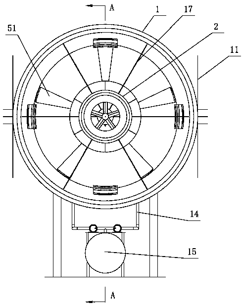
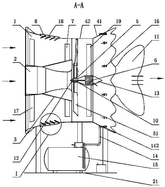
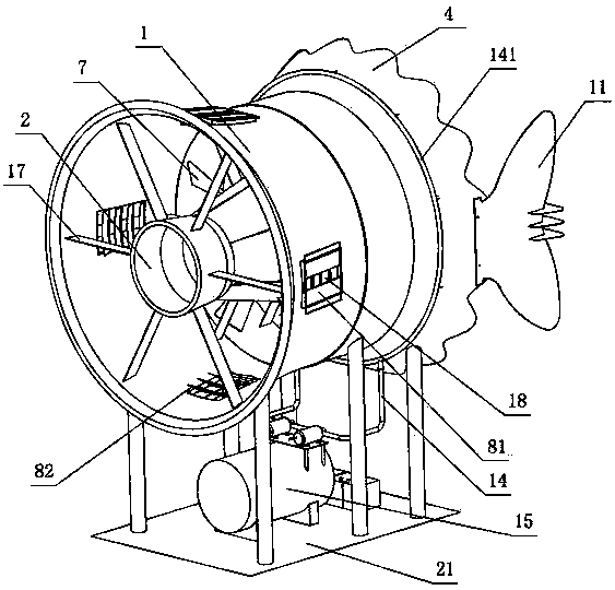
[0042] See figure 1 , figure 2 , image 3 , the present invention includes an outer narrow tube 1, an inner narrow tube 2 is integrally sleeved in the outer narrow tube 1, a taper sleeve 3 is fixedly connected to the outer peripheral surface of the inner narrow tube 2, and the wide head end of the taper sleeve 3 is located at the outer narrow tube 1 and the tapered sleeve 3 is provided with a guide vane 7, the inner narrow tube 2 and the tapered sleeve 3 are fixedly supported in the outer narrow tube 1, specifically, the front outer peripheral surface of the inner narrow tube 2 and the inner peripheral surface of the outer narrow tube 1 A plurality of first support plates 17 are connected between them, and a plurality of guide vanes 7 are connected between the outer peripheral surface of the taper sleeve 7 and the inner peripheral surfa...


PUM


Abstract

The invention discloses a straight-through type narrow-pipe wind collecting wind power generation system which comprises an outer narrow pipe. An inner narrow pipe is overall sleeved with the outer narrow pipe, a conical sleeve is fixedly connected to the peripheral face of the inner narrow pipe, the wide head end of the conical sleeve is located at the tail of the outer narrow pipe, guide vanes are arranged on the conical sleeve, the inner narrow pipe and the conical sleeve are fixedly supported in the outer narrow pipe, an air outlet of the inner narrow pipe is an external expansion opening, a wake flow pipe is axially and fixedly connected to the air outlet end of the outer narrow pipe, an impeller and a power generator are installed in the wake flow pipe, the impeller is close to the tail of the outer narrow pipe, blades on the impeller rotate under the driving effect of wind power to drive the power generator to generate power, and an external expansion section is arranged on the wake flow pipe. According to the straight-through type narrow-pipe wind collecting wind power generation system, on the basis that the inner-pipe wind speed is effectively quickened, the wind power use rate can be further improved, and the efficiency of the power generator can be further improved; meanwhile, due to the arrangement of a fogging machine, fogging is achieved through self-supplying of green electric energy, haze and dust are finally reduced through fogging, the atmospheric environment is improved, and therefore application of the wind power generation system is expanded.

Description

technical field [0001] The invention relates to the technical field of wind power generation equipment, in particular to a wind-gathering type wind power generation device, in particular to a straight-through narrow-tube wind-gathering wind power generation system capable of controlling fog and haze. Background technique [0002] The wind-gathering wind generator produced according to the narrow tube effect has broad application prospects in the field of wind power generation technology because of its advantages of gathering wind energy, boosting pressure and increasing speed, and improving wind energy utilization. The current wind gathering type wind power generation device usually sets the air inlet as a converging narrow tube to increase the wind speed. Since the wind is the result of air flow due to the pressure difference between different positions, the wind flows in the narrow tube. During the process, the flow rate will be affected by the resistance of the inner wall...

Claims


Application Information

Patent Timeline
IPC IPC(8): F03D9/00F03D3/04F03D3/06F03D11/00
CPCY02E10/74
Inventor 李勇强姚伯龙陈东辉赵磊徐泉根
Owner 无锡金蝎中蕴风电科技有限公司
Learn More