Clamping sleeve type metal sealing pipe joint and using method thereof

A metal seal and ferrule-type technology, which is applied in the direction of sealing surface connection, pipe/pipe joint/pipe fitting, passing components, etc., can solve the problem that the safe operation of the vehicle cannot be guaranteed, the structure of the double ferrule is complicated, and the reliability cannot be guaranteed. and other issues to achieve the effect of ensuring repeated times, safe and reliable sealing performance, and reliable work

Active Publication Date: 2014-05-21
CRRC QINGDAO SIFANG CO LTD
View PDF8 Cites 8 Cited by
  • Summary
  • Abstract
  • Description
  • Claims
  • Application Information

AI Technical Summary

Problems solved by technology

The structural tightness, anti-loosening and anti-vibration properties of the double ferrule pipe joint have been greatly improved. However, the double ferrule type has a complicated structure and is completely manually operated, so the reliability of the installation cannot be guaranteed. For the air brake pipeline of rail vehicles such as subways, the safe operation of the vehicle cannot be guaranteed

Method used


Image

  • Clamping sleeve type metal sealing pipe joint and using method thereof
  • Clamping sleeve type metal sealing pipe joint and using method thereof
  • Clamping sleeve type metal sealing pipe joint and using method thereof

Examples


Embodiment 1

[0069] Example 1: straight-through joint assembly

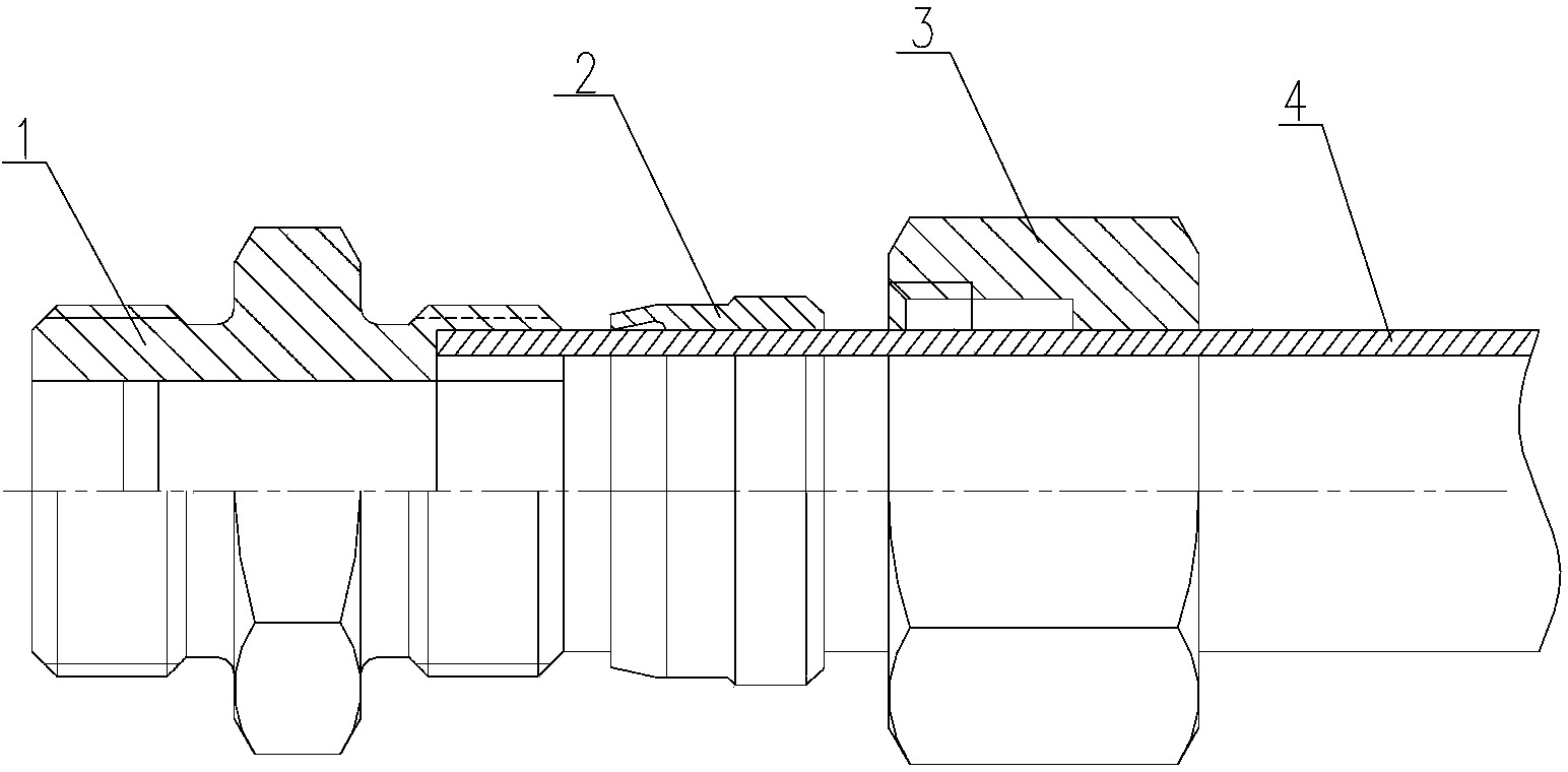
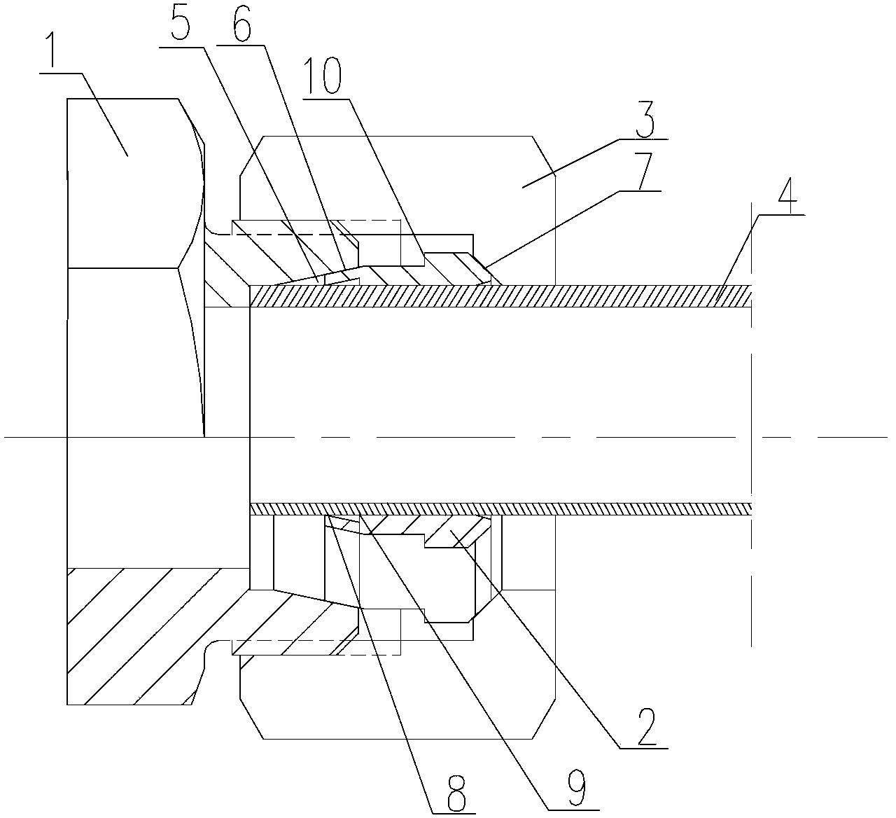
[0070] Such as Figure 5 As shown, the main body is two pipes 4 that need to be connected. The ends of each pipe 4 are respectively provided with nuts 3 and ferrules 2, and are connected by a joint body 1 in the middle. The joint body 1 is a straight-through joint, and the joint body 1 Both sides of the joint body 1 have external threads connected with the nut 3, and each side has a tapered hole 5 matching the ferrule 2, and the two ends of the joint body 1 are respectively connected to two pipes through a ferrule-type metal seal connection.

Embodiment 2

[0071] Embodiment 2: right-angle joint assembly

[0072] Such as Figure 6 As shown, the main body is two pipes 4 that need to be connected. The ends of each pipe 4 are respectively provided with nuts 3 and ferrules 2, and are connected by a joint body 1 in the middle. The joint body 1 is a right-angle joint, and the joint body 1 Each of the two ends of the joint body 1 has an external thread connected with the nut 3, and each of the two ends has a tapered hole 5 matched with the ferrule 2. The two ends of the joint body 1 are respectively connected to two pipes through a ferrule-type metal seal connection.

Embodiment 3

[0073] Embodiment 3: Tee joint assembly

[0074] Such as Figure 7 As shown, the main body is three pipes 4 that need to be connected. The ends of each pipe 4 are respectively provided with nuts 3 and ferrules 2. The middle is connected by a joint body 1. The joint body 1 is a three-way joint. The joint body 1 Each of the three ends of the joint body 1 has an external thread connected with the nut 3, each of the three ends has a tapered hole 5 matching the ferrule 2, and each of the three ends of the joint body 1 is connected by a ferrule-type metal seal. Three pipes are connected.


PUM


Abstract

The invention relates to a clamping sleeve type metal sealing pipe joint and a using method thereof. The clamping sleeve type metal sealing pipe joint comprises a joint body, a clamping sleeve and a nut, wherein the joint body and the nut are in threaded connection, the clamping sleeve is arranged between the joint body and the nut, the clamping sleeve is a metal piece, the clamping sleeve is provided with a front cutting edge and a rear cutting edge, the front end of the clamping sleeve is matched with a conical surface of the joint body, the rear end of the clamping sleeve is matched with a conical surface of the inner surface of the nut, and sealing is realized by enabling the front cutting edge and the rear cutting edge to be cut in the outer wall of a pipe. According to the clamping sleeve type metal sealing pipe joint disclosed by the invention, the structure of two cutting edges is adopted, the sealing performance is more reliable, the anti-shock performance and the anti-vibration performance are more excellent, and the service life is long.

Description

technical field [0001] The invention relates to a ferrule-type pipe joint, in particular to a ferrule-type metal sealing pipe joint used on an air brake pipeline of an urban rail vehicle and a method for using the same. Background technique [0002] With the development of science and technology, the scope of application of the pipeline system is becoming wider and wider, and it is widely used in all walks of life. Higher requirements are also put forward for the safety and reliability of the performance and pipeline system. The connecting device between pipes commonly used in the pipeline system is the pipe joint, and the basic forms of the pipe joint are flared type, welded type and ferrule type. Among them, the ferrule-type pipe joint has the characteristics of simple structure, convenient use and no welding. It is a convenient, reliable, and easy-to-install and disassemble connection method for medium and high-pressure pipelines. Corresponding sealing structures are ar...

Claims


Application Information

Patent Timeline
Patent Type & Authority Applications(China)
IPC IPC(8): F16L19/08
CPCF16L19/083
Inventor 李云峰周建乐孙忠选
Owner CRRC QINGDAO SIFANG CO LTD
Why Eureka
Try Eureka