Combustor used for gas stove

A technology for burners and gas stoves, applied in the field of kitchen appliances, can solve problems such as the inability to replenish air in time, and achieve the effects of solving uneven mixing, improving combustion sufficiency, and solving technical bottlenecks

Active Publication Date: 2014-05-21
刘申昌
View PDF5 Cites 4 Cited by
  • Summary
  • Abstract
  • Description
  • Claims
  • Application Information

AI Technical Summary

Problems solved by technology

Most of the existing gas cooker burners have one gas mixing chamber, and some manufacturers have 3 to 5 chambers. However, the distribution of the fire holes on the fire cover is usually along the circumference, and some manufacturers distribute along the radial direction. Since the air cannot be replenished to the burning gas in time, the thermal efficiency of the burner used in the current stove has reached the limit of 60% (GB16410-2007)

Method used


Image

  • Combustor used for gas stove
  • Combustor used for gas stove
  • Combustor used for gas stove

Examples


Embodiment 1

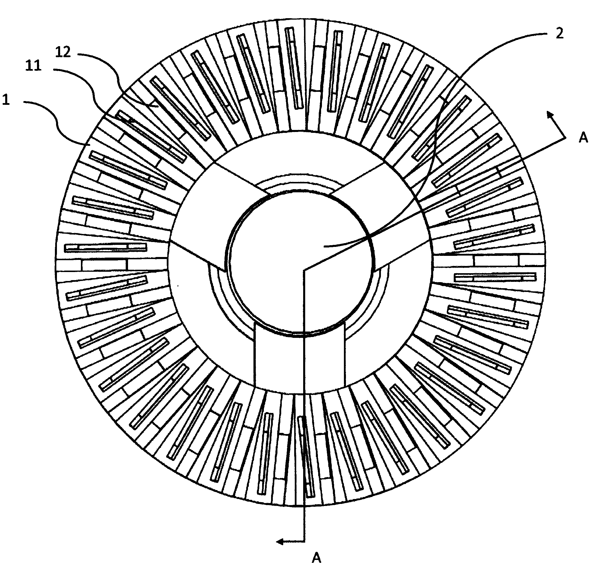
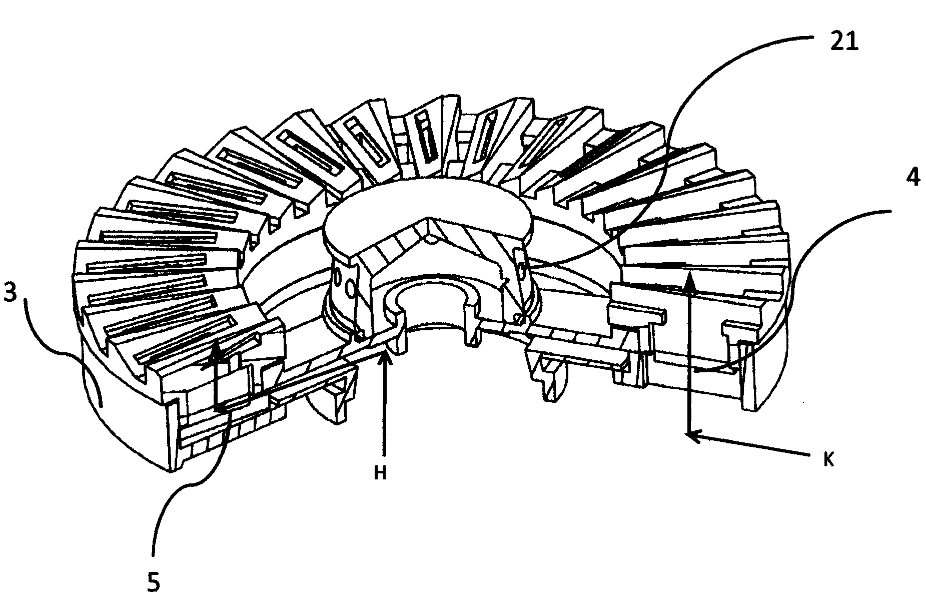
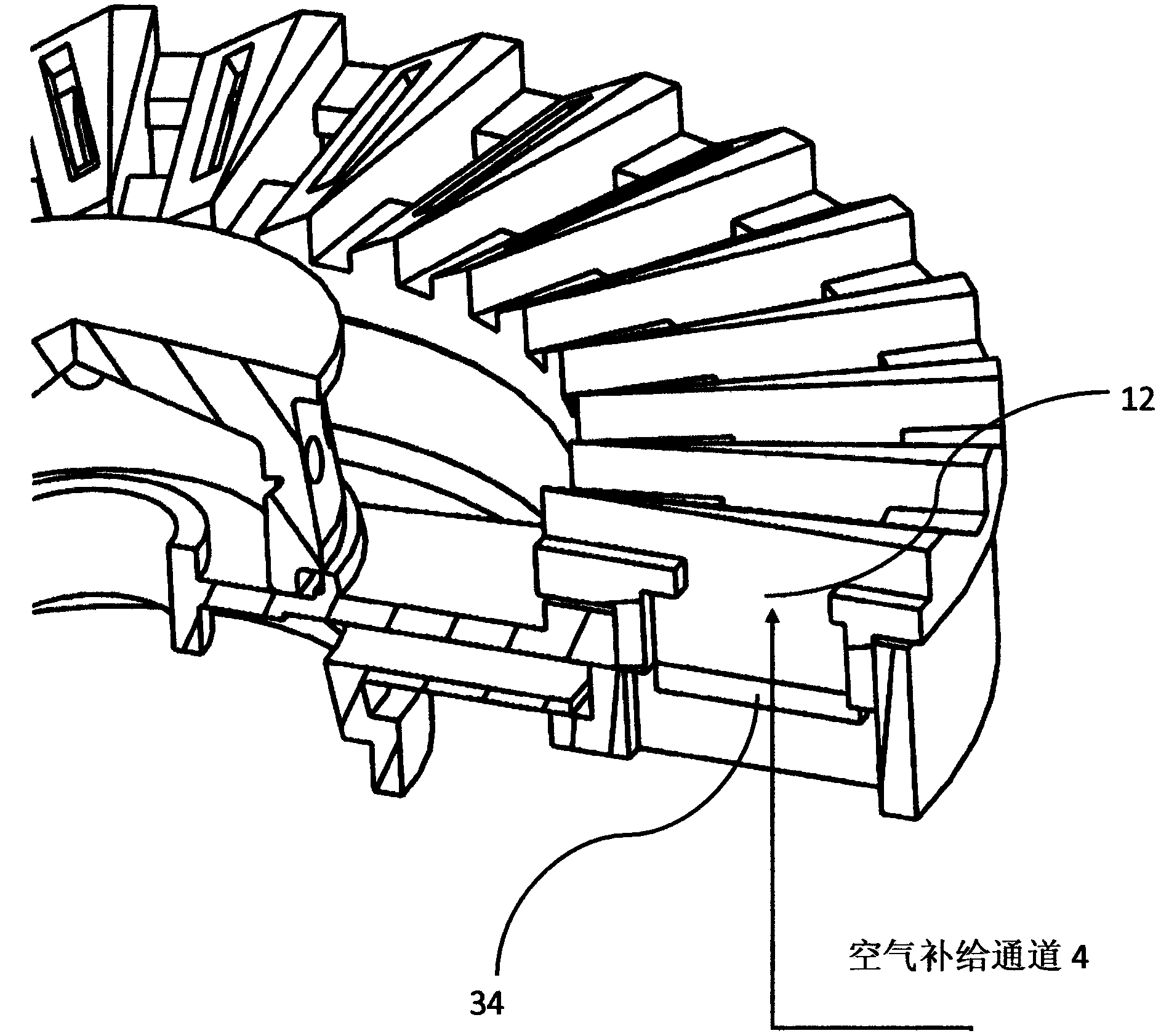
[0021] Example 1, such as figure 1 , figure 2 , image 3 , Figure 4 with Figure 5 As shown, the burner in this embodiment includes a large fire cover 1, a small fire cover 1 and a base 3. The large fire cover 1 has a fire outlet 11, an air supply channel 12 and a gas mixing chamber 13. The base 3 is a component base, which contains Base inner ring 31 , base outer ring 32 , gas mixing chamber 33 and air supply channel 34 .

[0022] Example 1, such as figure 2 with Figure 4 As shown, the gas mixing chamber 13 of the large fire cover 1 and the gas mixing chamber 33 on the base outer ring 32 of the base 3 are mechanically matched to form an integral gas mixing chamber 5 after being closely matched. The distribution of the fire holes on the fire cover should be distributed accordingly, and the number will also be designed into multiple independent gas mixing chambers according to the size of the burner and the number of fire holes in the fire cover.

[0023] Example 1, ...

Embodiment 2

[0025] Example 2, such as Image 6 , Figure 7 , Figure 8 , Figure 9 with Figure 10 As shown: the burner in this embodiment includes a large fire cover 1, a small fire cover 1 and a base 3. The large fire cover 1 has a fire outlet 11, an air supply channel 12 and a gas mixing chamber 13. The base 3 is a separate base, which contains The gas mixing chamber 35 and the air supply channel 36; the formation structure of the gas mixing chamber 5 and the air supply channel 4 is the same as that of the first embodiment. The airflow direction of the mixed gas and the air supply airflow direction refer to Example 1.


PUM


Abstract

The invention relates to a combustor used for a gas stove. The combustor comprises a big fire cover, a small fire cover and a base, and is characterized in that fire outlet holes, air supply passageways and gas mixing cavities are formed in the big fire cover, fire outlet holes are formed in the small fire cover, a base inner ring and a base outer ring are arranged on the base, and gas mixing cavities and air supply passageways are formed in the base outer ring. The air supply passageways of the big fire cover are matched with the air supply passageways in the base outer ring to form integral air supply passageways. The gas mixing cavities in the big fire cover are matched with the gas mixing cavities of the base to form integral gas mixing cavities. According to the combustor, mixed gas is mixed in the mixing cavities and combusted in the fire outlet holes of the fire covers, sufficient air supply is conducted through the air supply passageways, and therefore the mixed gas can be sufficiently combusted, and the technical effects of improving the heat flux and the heat efficiency of the combustor are achieved.

Description

technical field [0001] The patent of the present invention relates to a burner, which is applied to household gas stoves and integrated stoves, and belongs to the technical field of kitchen utensils Background technique [0002] From the perspective of national policies and residents' needs, low carbon emissions and low energy consumption have become a more important topic in civil gas appliances and a trend in future technological development. Most of the existing gas cooker burners have one gas mixing chamber, and some manufacturers have 3 to 5 chambers. However, the distribution of the fire holes on the fire cover is usually along the circumference, and some manufacturers distribute along the radial direction. Since the air cannot be replenished to the burning gas in time, the thermal efficiency of the burner used in the current stove has reached the limit (GB16410-2007). Contents of the invention [0003] The technical problem to be solved by the present invention is ...

Claims


Application Information

Patent Timeline
Patent Type & Authority Applications(China)
IPC IPC(8): F23D14/02F23D14/62F23D14/46
Inventor 刘申昌
Owner 刘申昌
Why Eureka
Try Eureka