High temperature resistance large load fiber sensing device

A technology of optical fiber sensing and large load, which is applied in the direction of measuring devices, instruments, weighing, etc., can solve the problems of sensing devices not durable, molten steel splashing, hidden dangers, etc., to simplify the installation and debugging procedures, and reduce processing and production costs , low cost effect

Inactive Publication Date: 2014-05-21
XIAN JINHE OPTICAL TECH
View PDF0 Cites 1 Cited by
  • Summary
  • Abstract
  • Description
  • Claims
  • Application Information

AI Technical Summary

Problems solved by technology

[0002] In the process of smelting steel, it is necessary to weigh the molten steel in the ladle. Since the temperature of the molten steel is more than 1600 degrees and the weight of the ladle is between 100 and 500 tons, the temperature and weight have a great influence on the weighing sensor device. There is even splashing of molten steel, all of which put forward higher requirements for the load sensing device, so that the existing sensing device based on the principle of resistance strain cannot be durable, thus causing hidden dangers in ensuring safe production and improving product quality

Method used


Image

  • High temperature resistance large load fiber sensing device
  • High temperature resistance large load fiber sensing device

Examples


Embodiment Construction

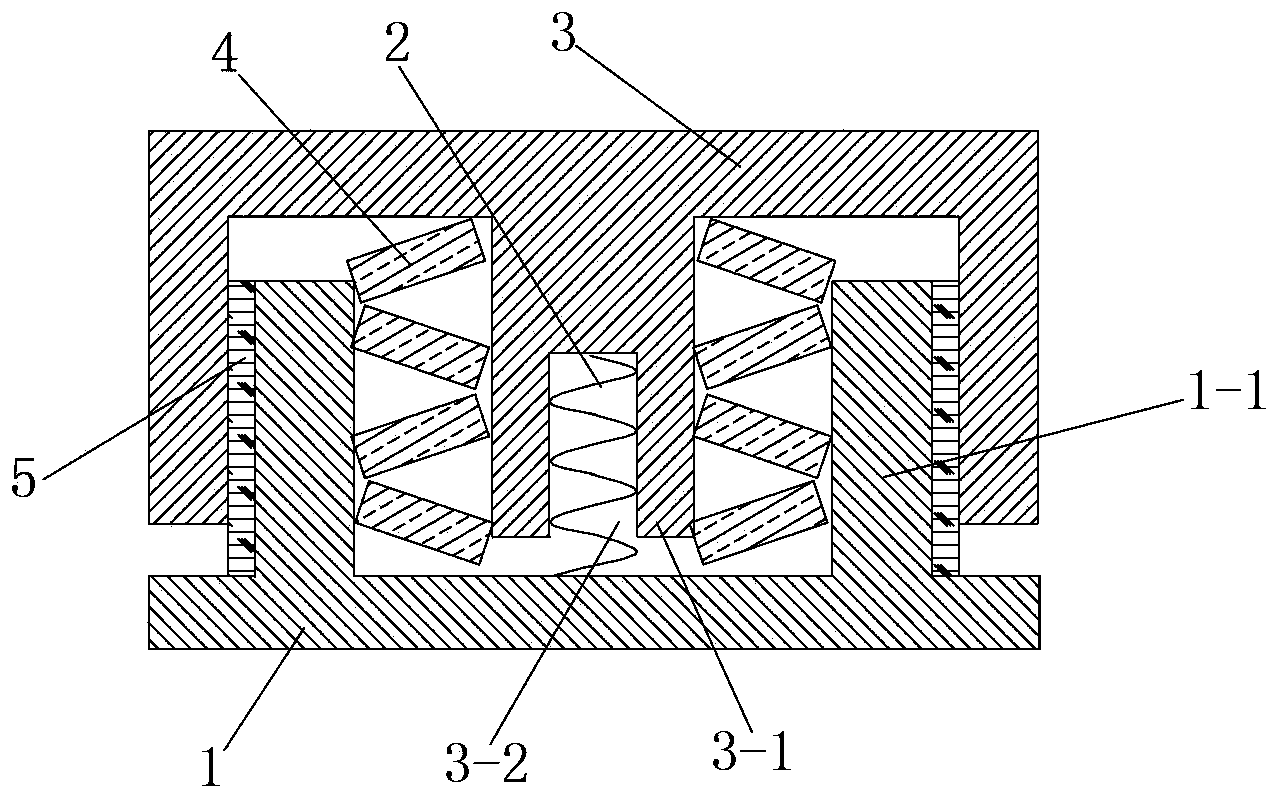
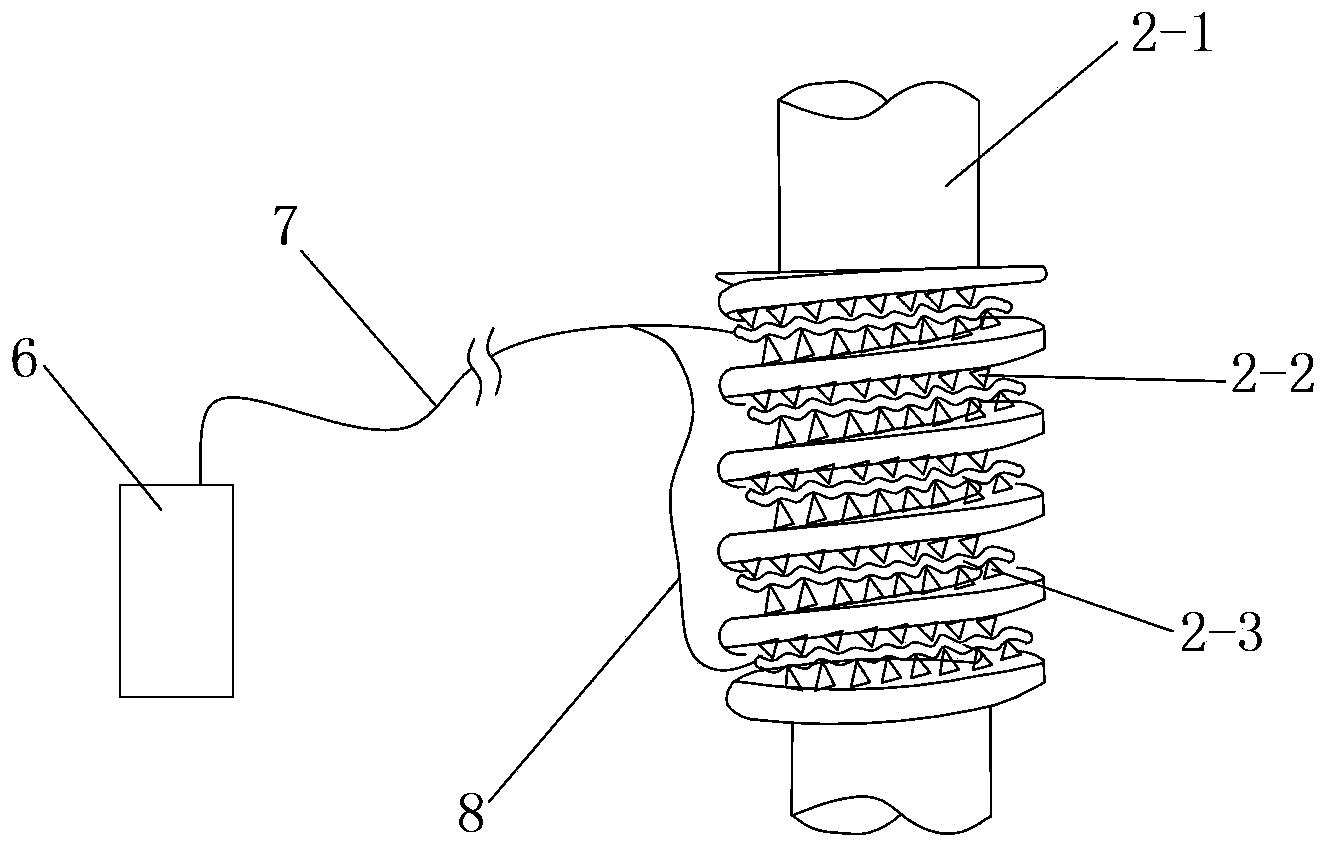
[0022] like figure 1 and figure 2 A high-temperature-resistant and heavy-load optical fiber sensing device shown includes a base 1 and an upper cover 3 covered on the base 1. A sleeve 1-1 is integrally formed on the base 1. The upper cover The bottom surface of 3 is provided with a connecting column 3-1, and the connecting column 3-1 is integrally formed with the upper cover 2, and the connecting column 3-1 is located inside the sleeve 1-1, and the lower part of the connecting column 3-1 The end face is provided with a vertically arranged blind hole 3-2, and the optical fiber bending sensing unit 2 is arranged in the blind hole 3-2, and the optical fiber bending sensing unit 2 includes a curved bracket 2-1, and the curved The upper end of the bracket 2-1 abuts against the top surface of the blind hole 3-2, the lower end of the curved bracket 2-1 is fixed on the top surface of the base 1, and the opposite sides of the curved bracket 2-1 A plurality of A-side deformed teeth 2...


PUM


Abstract

The invention discloses a high temperature resistance large load fiber sensing device. The high temperature resistance large load fiber sensing device comprises a base seat and an upper cover, wherein a sleeve is formed on the base seat through one body molding, a bottom surface of the upper cover is provided with a connection column, the connection column is arranged in the sleeve, a lower end face of the connection column is provided with a blind hole, the blind hole is internally provided with a fiber bending sensing unit, the fiber bending sensing unit comprises a curve type support, two opposite sides of the curve type support are provided with multiple A-side deformation teeth and multiple B-side deformation teeth, the multiple A-side deformation teeth and the multiple B-side deformation teeth are distributed in a staggered mode, a curve type channel for penetration of a signal fiber is arranged between head portions of the multiple A side deformation teeth and the multiple B side deformation teeth, the signal fiber is connected with a test unit through a transmission fiber, a connection column is provided with a disk spring, and the sleeve is sleeved with a sleeve tube in close fitting with an inner side wall of the upper cover. The high temperature resistance large load fiber sensing device has advantages of high temperature resistance, high load impact bearing capability and long service life and is suitable for a weighing sensing system for a steel-making ladle.

Description

technical field [0001] The invention relates to an optical fiber sensing device, in particular to a high temperature resistant and heavy load optical fiber sensing device. Background technique [0002] In the process of smelting steel, it is necessary to weigh the molten steel in the ladle. Since the temperature of the molten steel is more than 1600 degrees and the weight of the ladle is between 100 and 500 tons, the temperature and weight have a great influence on the weighing sensor device. There is even molten steel splashing, which all put forward higher requirements for the load sensing device, so that the existing sensing device based on the principle of resistance strain cannot be durable, thereby causing hidden dangers in ensuring safe production and improving product quality. Contents of the invention [0003] The object of the present invention is to overcome the shortcomings of the above-mentioned prior art and provide a high-temperature-resistant and heavy-load...

Claims


Application Information

Patent Timeline
Patent Type & Authority Applications(China)
IPC IPC(8): G01G17/04
Inventor 杜兵
Owner XIAN JINHE OPTICAL TECH
Why Eureka
Try Eureka