Test equipment for partial discharge of variable-frequency resonant cable based on optical electric field transducer
A technology of optical electric field and partial discharge, applied in the direction of testing dielectric strength, etc., to avoid misdiagnosis or missed diagnosis, improve the efficiency and accuracy of on-site testing, and the effect of fast waveform response frequency
- Summary
- Abstract
- Description
- Claims
- Application Information
AI Technical Summary
Problems solved by technology
Method used
Image

Examples
Embodiment Construction
[0017] The present invention will be further described below in conjunction with the accompanying drawings and specific implementation.
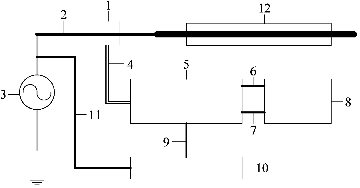
[0018] The present invention is based on the structure of the partial discharge test equipment of frequency conversion resonant cable of optical electric field sensor such as figure 1 As shown, the device consists of an optical electric field sensor 1, a high voltage wire 2, a variable frequency resonant power supply 3, a high voltage optical fiber 4, a photoelectric conversion and output device 5, a synchronous signal transmission line 6, a partial discharge signal transmission line 7, a partial discharge test instrument 8, and a high voltage measurement signal A transmission line 9, a voltage regulation control device 10, a voltage regulation signal transmission line 11, and a sample 12 are formed.
[0019] The optical electric field sensor 1 can meet the performance requirements of optical detection in a high-voltage environment, and refl...
PUM
 Abstract
Description
Claims
Application Information
 - Generate Ideas
- Intellectual Property
- Life Sciences
- Materials
- Tech Scout
- Unparalleled Data Quality
- Higher Quality Content
- 60% Fewer Hallucinations
Browse by: Latest US Patents, China's latest patents, Technical Efficacy Thesaurus, Application Domain, Technology Topic, Popular Technical Reports.
© 2025 PatSnap. All rights reserved.Legal|Privacy policy|Modern Slavery Act Transparency Statement|Sitemap|About US| Contact US: help@patsnap.com