Abnormal condition warning method

An abnormal state and abnormal technology, applied in hardware monitoring and other directions, can solve problems such as electrical characteristic failure, transaction amount, transaction item error, inability to conduct electronic transactions, etc., to avoid losses and prevent system instability.

Inactive Publication Date: 2014-05-21
CELESTICA TECH CONSULTANCY SHANGHAI
View PDF5 Cites 2 Cited by
  • Summary
  • Abstract
  • Description
  • Claims
  • Application Information

AI Technical Summary

Problems solved by technology

However, the user cannot immediately obtain the information of the failure of the power supply, which often results in a significant loss of commercial profits or irreparable loss of goodwill before the power supply is replaced or the backup power supply is activated.
[0003] In addition, for web servers that provide e-commerce services, in addition to configuring backup power supply units and multiple power supply units, it is also necessary to monitor whether the temperature of specific electronic components or areas exceeds the preset upper limit at any time, because the electrical components of electronic components The feature will malfunction due to overheating, resulting in the shutdown of the entire e-commerce service, affecting all online customers unable to conduct electronic transactions, or causing errors in transaction amounts and transaction items
[0004] In particular, general electronic systems use system events (System Event) to define specific events that will affect the normal operation of the system, such as central processing unit (CPU) overheating, fan abnormality, memory error or overheating, power supply (PSU) ) abnormality, battery overheating or abnormality, etc. Critical Events (Critical Events), however, the user cannot immediately know the occurrence of system events, and can only be known through special operations or the use of specific software, resulting in practical applications inconvenient

Method used


Image

  • Abnormal condition warning method
  • Abnormal condition warning method
  • Abnormal condition warning method

Examples


specific Embodiment approach

[0047] The embodiments of the present invention will be described in more detail below with reference to figures and symbol numbers, so that those skilled in the art can implement them after studying this specification.

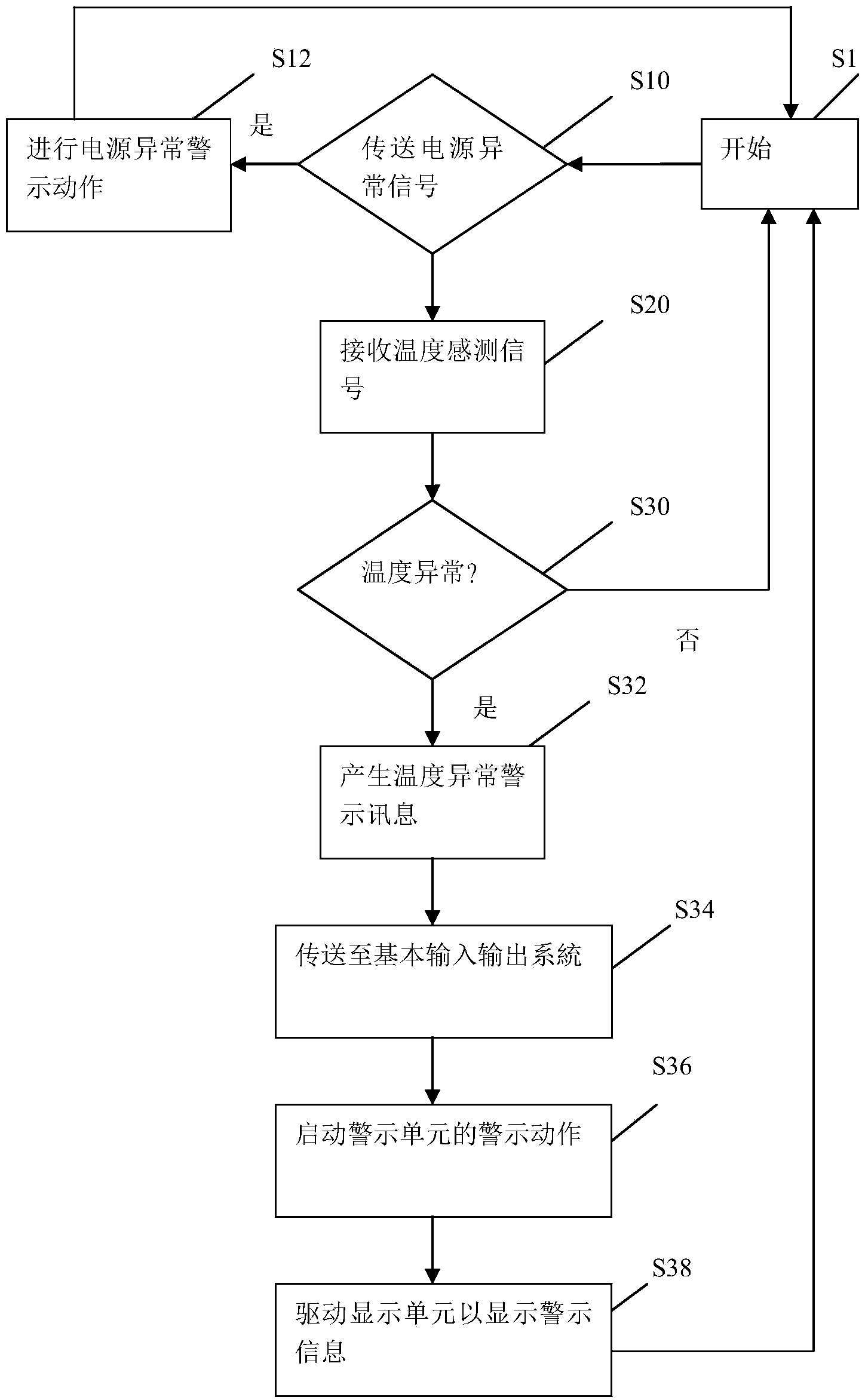
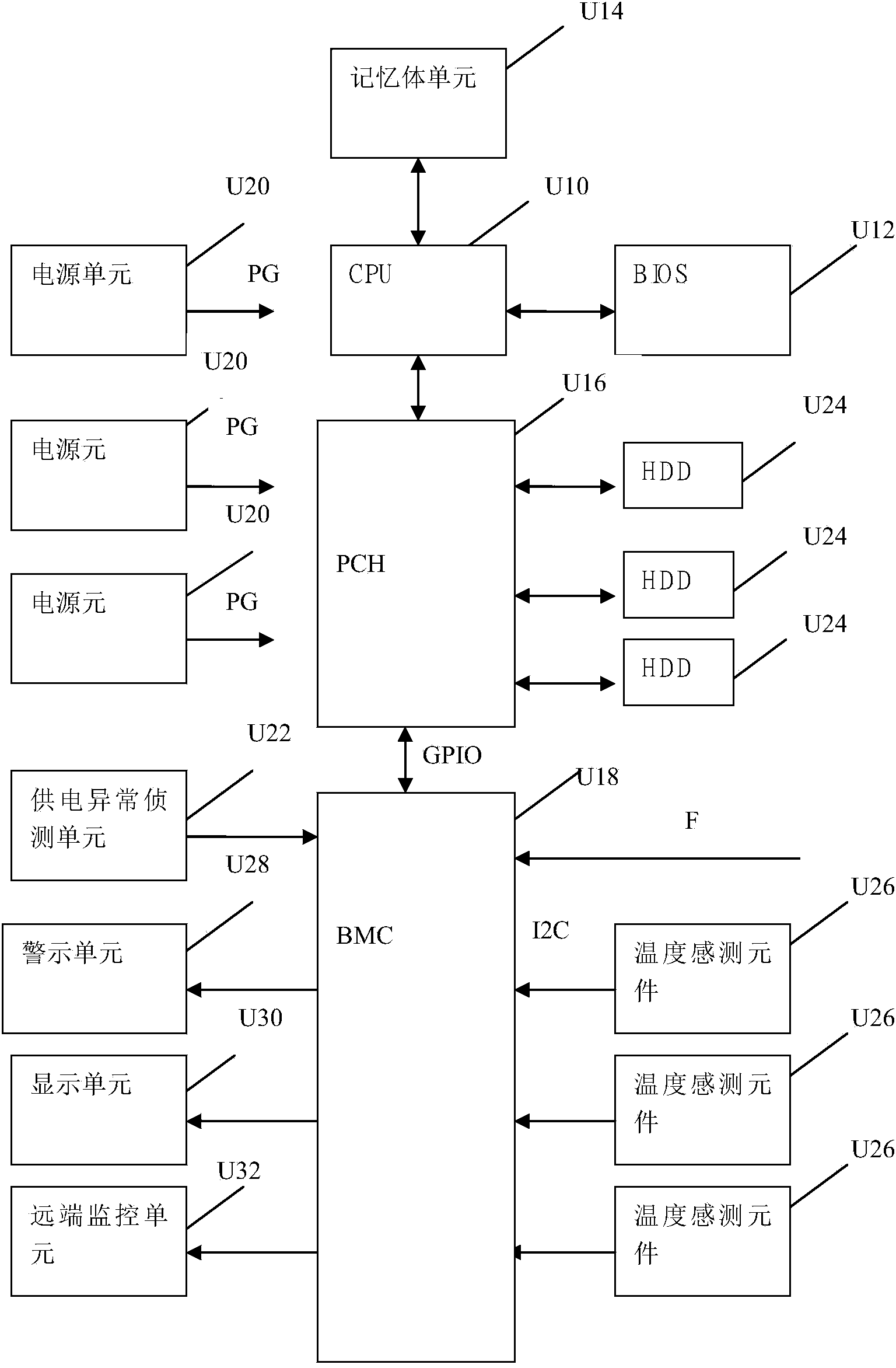
[0048] refer to figure 1 , is a schematic diagram of the operation flow of the abnormal state warning method according to the embodiment of the present invention. Such as figure 1 As shown, the abnormal state warning method of the present invention mainly includes steps S1, S10, S12, S20, S30, S32, S34, S36 and S38, which can provide a warning function when an abnormal state occurs in the system. Also for further reference figure 2, according to the system diagram of the abnormal state warning method of the embodiment of the present invention, it is characterized in that: the above-mentioned system includes a central processing unit (Central Processing Unit, CPU) U10, a basic input output system (Basic Input / Output System, BIOS) U12, a memory Body unit U1...


PUM


Abstract

The invention discloses an abnormal condition warning method used for informing operating personnel of abnormal conditions. The abnormal condition warning method includes the steps that whether an abnormal condition detection unit transmits a power supply abnormity signal or not is inspected; if yes, a control warning unit is started to carry out a power supply abnormity warning movement; if not, a baseboard management controller receives temperature sensing signals of each temperature sensing unit and judges whether temperature abnormity happens or not; if temperature abnormity happens, a temperature abnormity warning message is generated and transmitted to a basic input / output system; a warning action command is generated by the basic input / output system and transmitted to the baseboard management controller to start the preset warning movement of the warning unit; a warning display command is generated by the basic input / output system and transmitted to the baseboard management controller to drive a display unit to display the corresponding temperature abnormity warning message.

Description

technical field [0001] The present invention relates to an abnormal state warning method, especially to detect whether the temperature of a power supply and / or a specific component is abnormal, and use BIOS to initiate corresponding warning actions according to the abnormal type of the power supply and / or temperature. Background technique [0002] Electronic systems with high operational stability are often required in many places or application fields to provide long-term operation functions or e-commerce services. For example, telephone communication requires an electronic switch system that is not disconnected, so it is ensured that the caller and the receiver can talk and communicate at any time. Therefore, the electronic switch system needs to be equipped with a backup power supply When the power supply of the power supply is unstable, the backup power supply or other power supplies can be activated to provide the required power to maintain the normal operation of the e...

Claims


Application Information

Patent Timeline
Patent Type & Authority Applications(China)
IPC IPC(8): G06F11/32
Inventor 郭鹏霄张耀文黄奎彬
Owner CELESTICA TECH CONSULTANCY SHANGHAI
Why Eureka
Try Eureka