Manufacturing device and manufacturing method of battery pole plate

A battery electrode plate and manufacturing device technology, applied in electrode manufacturing, battery electrode, spray manufacturing, etc., can solve the problems of complex process method, complex process, poor environmental friendliness, etc., and achieve simple process, uniform coating, and stable adhesion. Sex-enhancing effects

Inactive Publication Date: 2014-05-21
SHANGHAI JIAO TONG UNIV +1
View PDF7 Cites 2 Cited by
  • Summary
  • Abstract
  • Description
  • Claims
  • Application Information

AI Technical Summary

Problems solved by technology

Before the copper mesh and aluminum mesh are combined with the positive and negative electrode films of the battery, the electrode film needs to be coated on the PET (polyester resin) film, and then the conductive glue is coated on the mesh with a mesh gluer, and then three layers The composite machine transfers the positive and negative electrode films to the copper mesh and the aluminum mesh, and finally uses the PET film cleaning machine to clean the used PET film. High, poor environmental friendliness
[0005] The use of sintered wire, sputtered continuous film and other processes has the following technical problems: the use of sintered wire, sputtered continuous film and other processes needs to confirm and fix multiple process parameters in advance
The process method is complicated and the production efficiency is low

Method used


Image

  • Manufacturing device and manufacturing method of battery pole plate
  • Manufacturing device and manufacturing method of battery pole plate
  • Manufacturing device and manufacturing method of battery pole plate

Examples


Embodiment 1

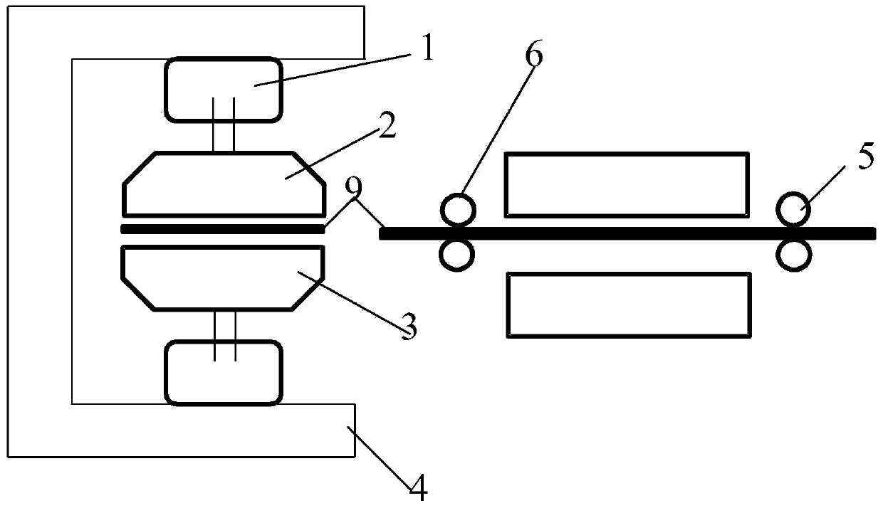
[0026] Such as figure 1 As shown, the battery pole plate manufacturing device (Example 1) of the present invention includes a mold fixture 1, a first upper mold 2, a first lower mold 3, a hydraulic press 4, a pole plate pulling device 5, a pole plate feeding device 6, and a battery The plate blank 9 is pulled by the plate pulling device, and the plate feeding device is sent between the first upper mold 2 and the first lower mold 3, and the first upper mold 2 and the first lower mold 3 are assembled in the mold fixture In 1, the mold clamp 1 is fixed on the hydraulic press 4, the first upper mold 2 and the first lower mold 3 are fixed molds, and the surface of the first upper mold 2 and the surface of the first lower mold 3 have concavo-convex shapes that cooperate with each other. For example, the mold can adopt a flat plate device with concave lines, and the above-mentioned lower mold needs to use a flat plate device with convex lines. According to the characteristics of the ...

Embodiment 2

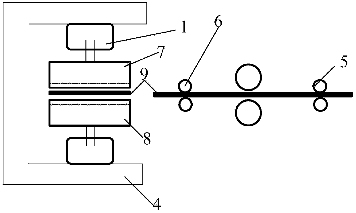
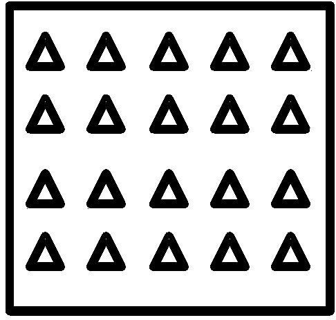
[0032] Such as figure 2 As shown, the second embodiment is basically the same as the first embodiment, the difference is that the second upper mold 7 and the second lower mold 8 are both rotating molds, and the second upper mold 7 can adopt a rotating mold with concave lines device, the second lower mold 8 needs to adopt a rotating mold device with convex lines, and according to the use characteristics of the rotating mold type mold, the concave lines of the second upper mold can be wave-shaped (Figure 3 (g)). The depth of the concave lines is 0.001 mm to 1 mm, and the distance between the central axes of the concave wavy shape is 1 mm to 10 mm. The rotary mold adopts continuous feeding method.


PUM

PropertyMeasurementUnit
depthaaaaaaaaaa

Abstract

The invention discloses a manufacturing device and a manufacturing method of a battery pole plate. The manufacturing device of the battery pole plate comprises a mould clamp, an upper mould, a lower mould, an oil press, a pole plate dragging device and a pole plate feeding device, wherein a battery pole plate blank is dragged by the pole plate dragging device and is conveyed between the upper mould and the lower mould by the pole plate feeding device; the upper mould and the lower mould are assembled in the mould clamp; the mould clamp is fixedly arranged on the oil press; mutually-matched concave-convex shapes are formed on the surface of the upper mould and the surface of the lower mould. The manufacturing device of the battery pole plate is simple in structure; the coating is uniform and the production efficiency is improved.

Description

technical field [0001] The invention relates to a battery technology, in particular to a manufacturing device and a manufacturing method of a battery pole plate. Background technique [0002] Batteries (such as lithium-ion batteries or lithium polymer batteries) are mainly composed of positive electrodes, negative electrodes, separators, electrolytes, etc., wherein the positive electrodes or negative electrodes are composed of active materials coated on the current collectors. The currently known current collectors are mainly as follows Three ways: (1) copper foil, aluminum foil, (2) copper mesh, aluminum mesh, (3) sintering a layer of metal wire on copper foil. For example, the Chinese patent No. CN95190724.7 discloses an improved battery plate and its manufacturing method. The battery plate includes many metal fibers of single or multiple diameters, and the fibers are randomly arranged and sintered to form the inner limit. Conductive battery plates with many micropores. ...

Claims


Application Information

Patent Timeline
Patent Type & Authority Applications(China)
IPC IPC(8): H01M4/04
CPCH01M4/0419H01M4/139Y02E60/10
Inventor 吴红杰赵征袁世斐殷承良罗英
Owner SHANGHAI JIAO TONG UNIV
Why Eureka
Try Eureka