Time synchronization protocol system based on chain industrial Ethernet and synchronization method

A time synchronization protocol and Ethernet technology, which is applied in the field of communication, can solve the problems of reducing synchronization frequency, prolonging synchronization time, and low timestamp accuracy, achieving the effects of reducing measurement errors, increasing synchronization frequency, and improving recognition accuracy

Active Publication Date: 2014-05-21
南京航浦机械科技有限公司
View PDF5 Cites 23 Cited by
  • Summary
  • Abstract
  • Description
  • Claims
  • Application Information

AI Technical Summary

Problems solved by technology

[0005] However, the above-mentioned technologies adopt the method of real-time measurement and update dwell time when the transparent clock is used, which increases the load of the synchronization lumped frame, resulting in a significant extension of the synchronization time, and cannot fully integrate the synchronization process with repeated information communication, reducing the synchronization frequency. The measurement error of time information is large
Furthermore, when offset compensation is performed in the above-mentioned technology, drift and offset are not compensated separately. When the synchronization period is long, although the drift amount is negligible relative to the offset amount, it limits the further improvement of synchronization accuracy.
Finally, in the above technology, the time stamp acquisition is at the MAC layer, and cannot further advance to the physical layer (PHY), resulting in low precision of the acquired time stamp

Method used


Image

  • Time synchronization protocol system based on chain industrial Ethernet and synchronization method
  • Time synchronization protocol system based on chain industrial Ethernet and synchronization method
  • Time synchronization protocol system based on chain industrial Ethernet and synchronization method

Examples


Embodiment Construction

[0045] The present invention will be described in detail below in conjunction with the accompanying drawings.

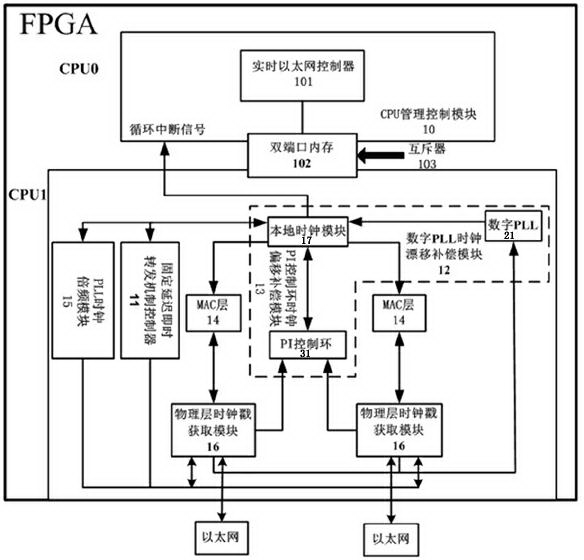
[0046] like figure 1 As shown, the time synchronization protocol system based on chained industrial Ethernet of the present invention is realized in FPGA, and FPGA adopts Cyclone IV GX series chip of Altera Company, model is EP4CGX30CF23C8. The FPGA not only integrates the Ethernet transceiver, but also has a large number of logic gates to realize all the synchronous system functions. Two CPUs (that is, CPU0 and CPU1) are constructed in this FPGA for different functions. CPU0 includes a CPU management control module 10, and the CPU management control module 10 is composed of a real-time Ethernet controller 101, a dual-port memory 102 and a mutex 103. , the real-time Ethernet controller 101 controls the reading and writing of the dual-port memory 102 through the mutex 103, shares the real-time information of the CPU1, manages the synchronization system and realizes t...


PUM


Abstract

The invention discloses a time synchronization protocol system based on a chain industrial Ethernet and a synchronization method, and belongs to the technical field of communication. Measuring errors are decreased by the aid of a fixed-delay instant forwarding mechanism controller and a PLL (phase locking loop) frequency multiplication module output high-frequency clock, clock drift compensation is realized by the aid of a digital PLL clock drift compensation module, clock offset compensation is realized by the aid of a PI (proportional-integral) control ring clock offset compensation module, modules are obtained by the aid of a physical layer clock timestamp, and the influence of random physical link delay on clock timestamp acquiring accuracy is decreased. Random variables affecting chain Ethernet clock synchronization accuracy are limited or cut down, and the clock synchronization accuracy is improved.

Description

technical field [0001] The invention relates to a time synchronization protocol system and synchronization method, especially a chain network time synchronization system and synchronization method based on a fixed delay forwarding mechanism, separate compensation for clock drift and clock offset, and clock stamp physical layer acquisition, belonging to the field of communication technology . Background technique [0002] In recent years, due to its development, high transmission rate, low hardware cost and many other advantages, Ethernet has been continuously applied in the field of industrial field, and has replaced the industrial field bus as the second generation of industrial communication technology; at the same time, according to the processing and manufacturing of the industrial field Accuracy requirements require high synchronization accuracy between clocks at Ethernet distribution sites. How to ensure the synchronization accuracy of Ethernet has become one of the k...

Claims


Application Information

Patent Timeline
Patent Type & Authority Applications(China)
IPC IPC(8): H04J3/06
Inventor 楼佩煌黄威然钱晓明刘明灯赵鹏张浩彭立军
Owner 南京航浦机械科技有限公司
Why Eureka
Try Eureka