Reference signal received power measurement method, device and terminal
A technology of reference signal and received power, applied in the field of communication
- Summary
- Abstract
- Description
- Claims
- Application Information
AI Technical Summary
Problems solved by technology
Method used
Image

Examples
Embodiment 1
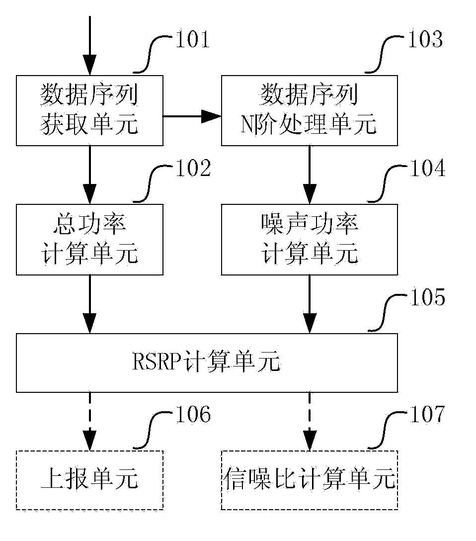
[0112] This embodiment introduces a measurement device for Reference Signal Received Power (RSRP), such as figure 1 As shown, it includes a data sequence acquisition unit 101, a total power calculation unit 102, a data sequence N-order processing unit 103, a noise power calculation unit 104 and an RSRP calculation unit 105, wherein:
[0113] The data sequence obtaining unit 101 is used to obtain M columns of data sequence y containing pilot information m (k), where k is 1 to K m The integer serial number of K m is the data sequence y m (k) length; m is an integer sequence number from 1 to M, and M is the number of data sequences;
[0114] The total power calculation unit 102 is configured to calculate the total power Power_Total of the reference signal and noise based on the data sequence;
[0115] The data sequence N-level processing unit 103 is configured to perform N-level processing on the data sequence, where N is a positive integer;
[0116] The noise power calculat...
Embodiment 2
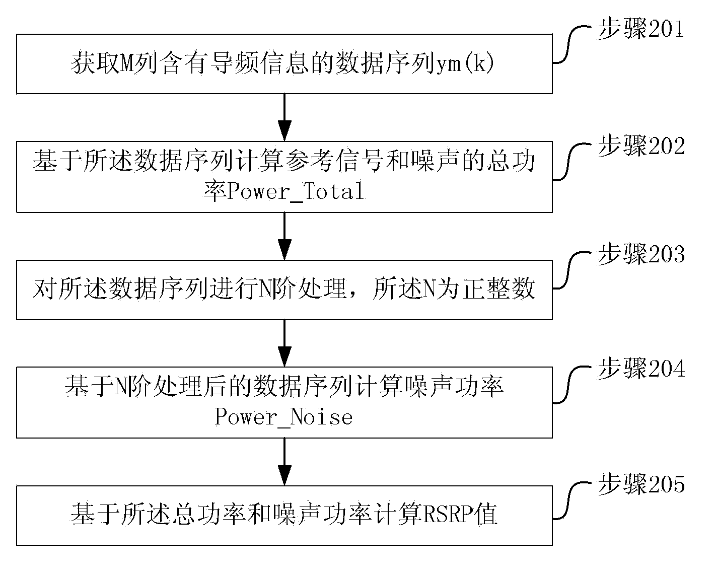
[0149] This embodiment introduces a RSRP measurement method, such as figure 2 shown, including:
[0150] Step 201, obtain M columns of data sequence y containing pilot information m (k), where k is 1 to K m The integer serial number of K m is the data sequence y m (k) length; m is an integer sequence number from 1 to M, and M is the number of data sequences;
[0151] Preferably, in the M column data sequence, the same column y m (k) Contains pilot information of the same transmit antenna port;
[0152] same column y m (k) Pilot information containing the same transmit antenna port refers to: the same column y m (k) is obtained after processing the information sequence received on the pilot time-frequency resource sequence of the same transmitting antenna port.
[0153] Get M columns of data sequence y containing pilot information m (k), including: acquiring M columns of data sequence y containing pilot information in the same subframe m (k); Or, obtain M column and ...
application example 1
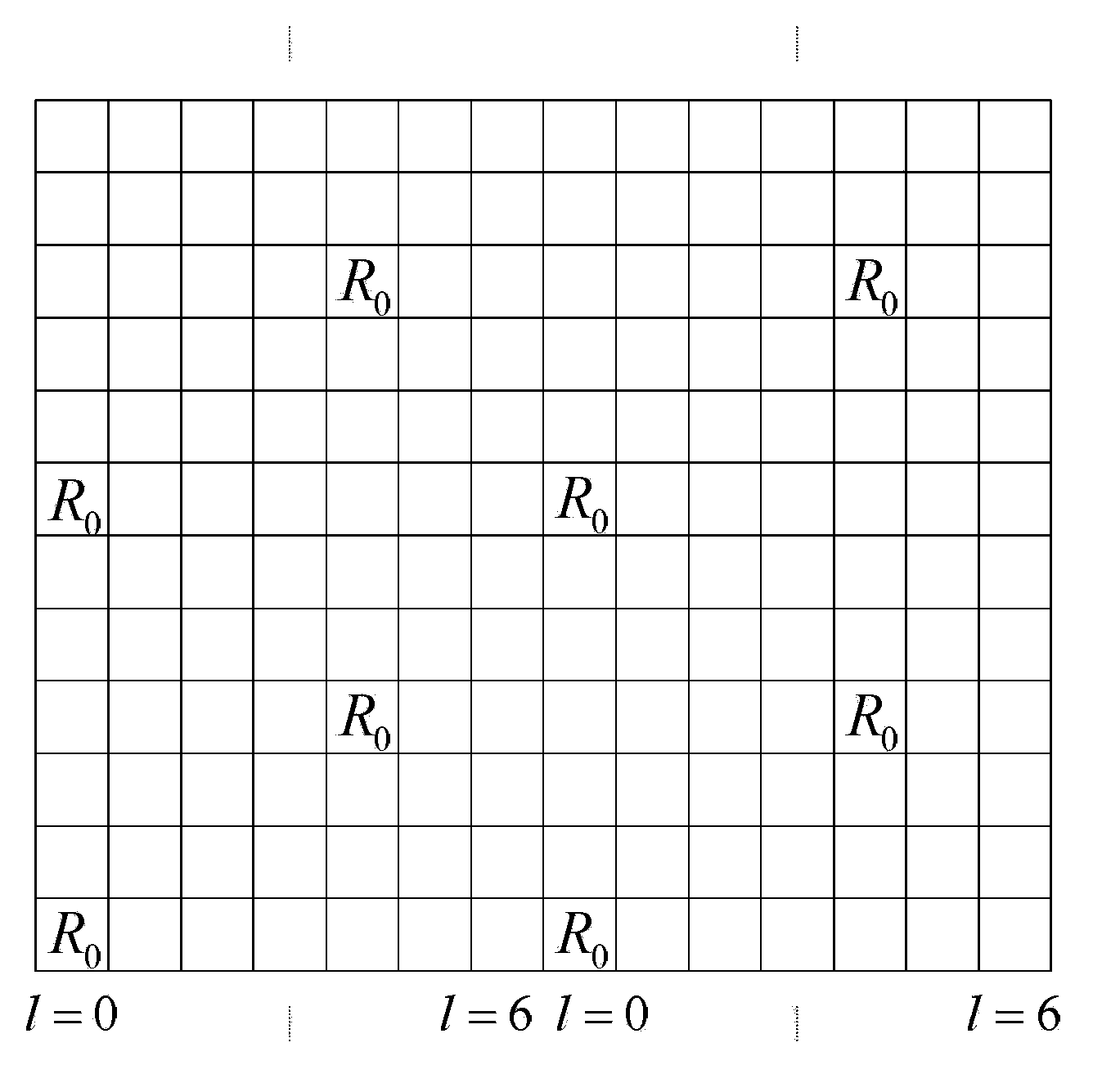
[0175] image 3 It is the CRS time-frequency resource diagram of the LTE downlink transmission mode. The direction of the abscissa is the direction of the time domain. The length of each small square represents the length of an OFDM symbol. The figure only shows the length of one subframe (a subframe contains There are 14 OFDM symbols); the ordinate direction is the frequency domain direction, the length of each small square represents the length of a subcarrier, and the figure only shows the length of a PRB (a PRB contains 12 subcarriers); each A grid represents a RE time-frequency resource.
[0176] image 3 , marked with "R 0 The time-frequency resource of " is the position where the pilot information transmitted by the antenna with the port number "0" is located. This time-frequency resource is called the pilot time-frequency resource. In this paper, the pilot time-frequency resource refers to the transmission Information time-frequency resources. Pilot signals are also...
PUM
 Abstract
Description
Claims
Application Information
 - R&D
- Intellectual Property
- Life Sciences
- Materials
- Tech Scout
- Unparalleled Data Quality
- Higher Quality Content
- 60% Fewer Hallucinations
Browse by: Latest US Patents, China's latest patents, Technical Efficacy Thesaurus, Application Domain, Technology Topic, Popular Technical Reports.
© 2025 PatSnap. All rights reserved.Legal|Privacy policy|Modern Slavery Act Transparency Statement|Sitemap|About US| Contact US: help@patsnap.com