Flow rate control device

A fluid control device and fluid technology, applied to valve devices, fuel injection devices, valve operation/release devices, etc., can solve problems such as the reduction of engine operating frequency, and achieve the effects of reducing piping, reducing costs, and suppressing pressure loss.

Active Publication Date: 2014-05-21
MITSUBISHI ELECTRIC CORP
View PDF6 Cites 6 Cited by
  • Summary
  • Abstract
  • Description
  • Claims
  • Application Information

AI Technical Summary

Problems solved by technology

[0003] In recent years, due to the HEV (Hybrid Electric Vehicle: Hybrid Electric Vehicle) of automobiles, the operating frequency of the engine has been reduced, and the opportunity for evaporation gas treatment has been reduced accordingly. However, with the strengthening of environmental restrictions, it is required to improve the evaporation gas treatment system. The ability to make the large flow rate in the low negative pressure area a technical problem

Method used


Image

  • Flow rate control device
  • Flow rate control device
  • Flow rate control device

Examples


Embodiment approach 1

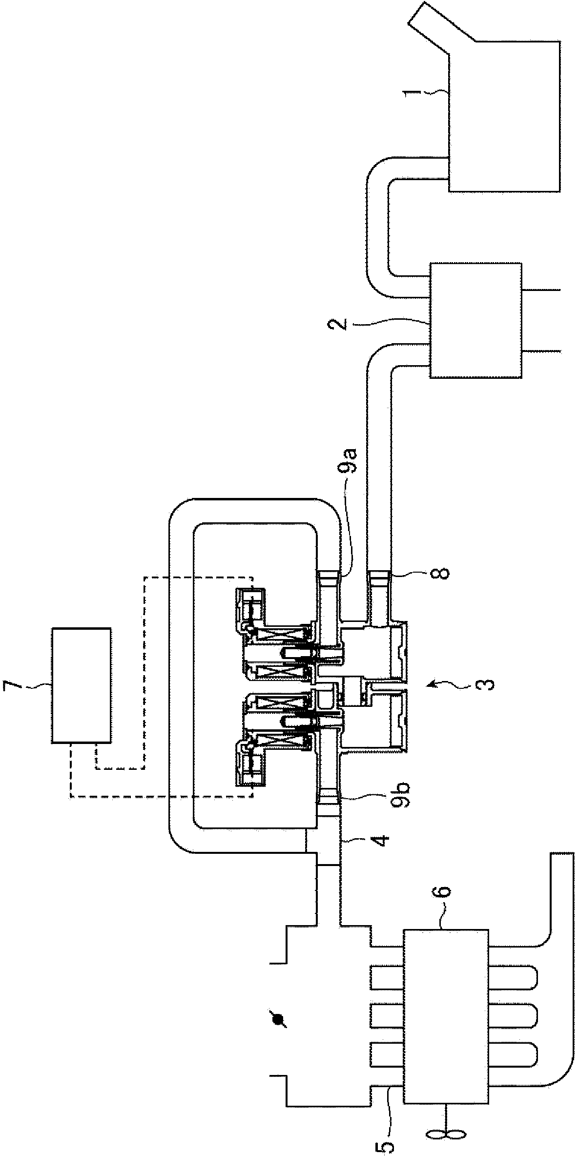
[0030] exist figure 1 In the shown boil-off gas treatment system, boil-off gas generated in a fuel tank 1 is temporarily adsorbed in a device called a carbon canister 2 using activated carbon. After the engine 6 is started, combustion occurs when the mixture of absorbed air and evaporated gasoline flows from the carbon canister 2 into the engine 6 due to the negative pressure of the intake manifold 5 . At this time, the flow control device 3 controls the flow rate of the air-fuel mixture introduced from the canister 2 to the engine 6 according to the driving signal of the control unit 7 .

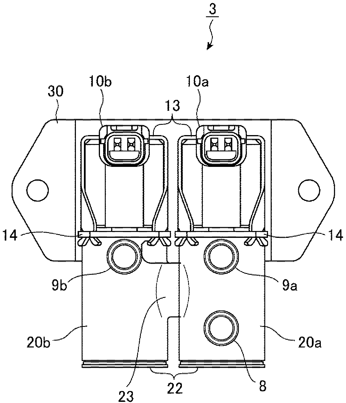
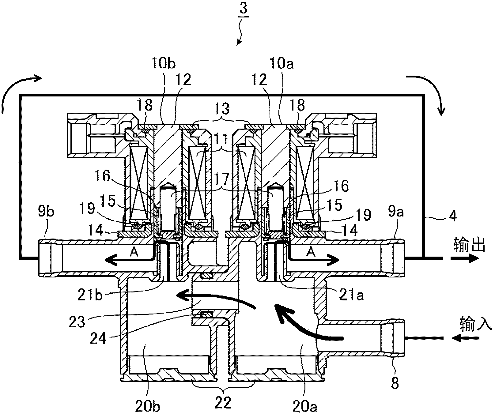
[0031] figure 2 is a front view showing the structure of the flow control device 3, image 3 is a sectional view. This flow control device 3 is a structural example in which two solenoid valves are combined, and one solenoid valve is constituted by the solenoid part 10a and the chamber 20a, and one solenoid valve is constituted by the solenoid part 10b and the chamber 20b. There is one...


PUM


Abstract

A flow rate control device is provided with an input port (8) connecting to the chamber (20a) of one of the two solenoid valves. Output ports (9a, 9b) are connected to the respective opening-closing passages (21a, 21b) of the two solenoid valves. The flow rate control device is also provided with a connection port (23) for connecting the chambers (20a, 20b), and this also allows fluid to flow to the chamber (20b), the fluid having been introduced into the chamber (20a) from the input port (8).

Description

technical field [0001] The invention relates to a flow control device connected with a plurality of electromagnetic valves. Background technique [0002] The car's boil-off gas treatment system temporarily absorbs the boil-off gas in the fuel tank to the carbon canister, and uses the negative pressure of the intake manifold to introduce the boil-off gas into the engine to make it burn again, preventing the boil-off gas from being discharged to the outside. The flow rate of boil-off gas introduced into the engine is controlled by a solenoid valve. [0003] In recent years, due to the HEV (Hybrid Electric Vehicle: Hybrid Electric Vehicle) of automobiles, the operating frequency of the engine has been reduced, and the opportunity for evaporation gas treatment has been reduced accordingly. However, with the strengthening of environmental restrictions, it is required to improve the evaporation gas treatment system. The ability to make the large flow rate in the low negative pres...

Claims


Application Information

Patent Timeline
Patent Type & Authority Applications(China)
IPC IPC(8): F16K31/06F16K27/02
CPCF16K27/0263F16K27/029F16K31/0624F02M25/0836F02M2025/0845F16K11/24
Inventor 垰佑太郎高桥正次
Owner MITSUBISHI ELECTRIC CORP
Why Eureka
Try Eureka