Anti-deposition pressure atomization nozzle

An atomizing nozzle and anti-deposition technology, which is applied to spray devices, spray devices, spray devices with movable outlets, etc., can solve the problems of large consumption of materials, unreasonable structure, difficult processing and manufacturing, etc. The effect of low loss and easy processing

Active Publication Date: 2014-05-28
NANJING LANSHAN ENVIRONMENTAL TECH
View PDF4 Cites 16 Cited by
  • Summary
  • Abstract
  • Description
  • Claims
  • Application Information

AI Technical Summary

Problems solved by technology

Most of the current pressure atomizing nozzles require high liquid pressure, and the structure is unreasonable, difficult to process and manufacture, and has disadvantages such as large material consumption, especially for the spray of solid-containing liquids, solids are very easy to deposit in the nozzle, long-term use , causing clogging or corrosion

Method used


Image

  • Anti-deposition pressure atomization nozzle
  • Anti-deposition pressure atomization nozzle
  • Anti-deposition pressure atomization nozzle

Examples


Embodiment approach

[0057] In specific implementation, the swirl vanes can have various forms and structures. Take the following implementations as examples:

example 1

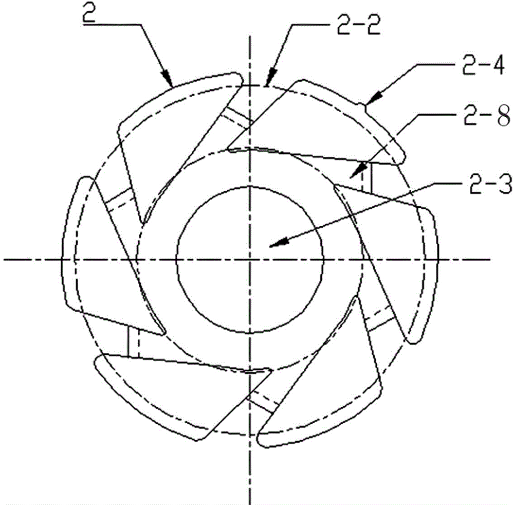
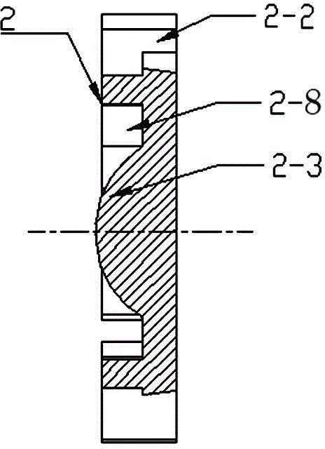
[0059] like figure 2 , image 3 , Figure 4 The circular swirl sheet shown has a circular groove in the center of the side plate facing the swirl atomization chamber, and six tangential grooves are evenly distributed along the periphery of the circular groove 2 -8, the tangential groove 2-8 communicates with the circular groove. The central portion of the circular groove is provided with an arc-shaped central protrusion 2-3.

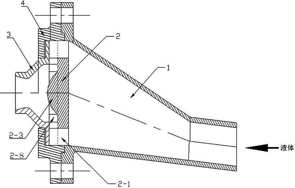
[0060] The outer edge of the tangential groove 2-2 is dug to the other side of the swirl plate 2 to form the liquid distribution groove 2-2. like image 3 As shown, the wall surface of the liquid distribution tank 2-2 is inclined toward the direction of the water inlet chamber 1, and is in the shape of a cone, and the horizontal inclination angle of the wall surface is ≥3°.

[0061] After the pressure liquid enters the tangential groove 2-8 from the liquid distribution groove 2-2, under the action of the tangential groove 2-8, it forms a swirl flow...

example 2

[0064] like Figure 5 , Figure 6 , Figure 7 As shown in a circular swirl sheet, an annular groove is provided on the center of the side plate facing the swirl atomization chamber, and six tangential grooves 2-8 are evenly distributed along the circumference. The inner circle of the groove protrudes upwards to form an arc-shaped central protrusion 2-3, and the tangential groove 2-8 is located on the periphery of the central protrusion 2-3 and communicates with the annular groove.

[0065] The outer side of the tangential groove 2-2 is provided with a liquid distribution hole 2-1 penetrating to the other side of the swirl sheet 2. like Figure 6 As shown, the wall surface of the liquid distributing hole 2-1 is inclined toward the water inlet chamber 1, and is in the shape of a truncated cone, with a cone angle ≥ 6°.

[0066] In the above embodiment, the central protrusion 2-3 of the swirl plate 2 can be integrally formed with the swirl plate body, or can be processed separ...


PUM


Abstract

An anti-deposition pressure atomization nozzle is characterized in that a nozzle inner cavity is separated into a water inlet chamber and a cyclone atomization chamber through a cyclone piece. The water inlet chamber is connected with the a water inlet pipe. The cyclone atomization chamber is provided with a atomization nozzle body. The bottom of the water inlet chamber is oblique. The horizontal height of inlet of the water inlet chamber is lower than the height of the outlet of the water inlet chamber. A plurality of liquid distribution holes or grooves which are evenly distributed are formed in the cyclone piece. The water inlet chamber is communicated with the cyclone atomization chamber through the liquid distribution holes or grooves. The lowest point of each liquid distribution hole or groove is not lower than the highest point of the bottom of the water inlet chamber. One side, facing the cyclone atomization chamber, of the cyclone piece is provided with a tangential slot which is communicated with the distribution holes or grooves. The anti-deposition pressure atomization nozzle has the advantages that pressurized liquid enters the tangential slot of the cyclone piece from the water inlet chamber through the liquid distribution holes or grooves, the liquid is fed into the cyclone atomization chamber in a high-speed tangential manner, and the liquid rotating at high speed leaves the nozzle and then dispersed to form droplet groups of certain particle size; the anti-deposition pressure atomization nozzle is simple in structure, less prone to deposition and blocking, convenient to machine and manufacture, good in atomizing effect, and low in energy loss.

Description

technical field [0001] The invention belongs to an atomizing nozzle device used in the industrial field, in particular to an anti-deposition pressure atomizing nozzle suitable for spraying solid-containing liquids. Background technique [0002] Atomization of a liquid refers to the physical process in which a liquid becomes a liquid mist or other small droplets in a gas environment under the action of external energy. Atomization technology has covered almost all industrial fields. In addition to the combustion of various fuels (gas, liquid and solid fuels), atomization technology is widely used in non-combustion industries such as catalytic granulation, food processing, powder coating, and pesticide spraying. etc. also have a wide range of applications. [0003] There are many kinds of liquid atomization methods, and the representative ones mainly include mechanical atomization, medium atomization, and special nozzle atomization. Mechanical atomization mainly relies on th...

Claims


Application Information

Patent Timeline
Patent Type & Authority Applications(China)
IPC IPC(8): B05B1/34
CPCB05B3/02
Inventor 罗三强凌斌聂江宁
Owner NANJING LANSHAN ENVIRONMENTAL TECH
Why Eureka
Try Eureka