Three-axis multi-head gantry machining equipment

A processing equipment and gantry technology, applied in the field of three-axis multi-head gantry processing equipment, can solve the problems of high-speed factory operation production, low production efficiency, low precision requirements, etc., to avoid too small clamping area and processing The effect of high precision and easy machine operation

Active Publication Date: 2014-05-28
TAICANG WEGOMA MACHINERY
View PDF7 Cites 6 Cited by
  • Summary
  • Abstract
  • Description
  • Claims
  • Application Information

AI Technical Summary

Problems solved by technology

[0002] At present, in the aluminum profile door and window processing industry, the milling of aluminum profiles is based on a single profile processing as the main processing form. For complex profiles, multiple end faces need to be processed, and the processing is based on fixed equipment and dynamic profiles. Every time the end face of a spatial position is processed, it needs to be taken out from the processing equipment, repositioned to adjust the positioning processing angle, and processed again. The processing operation is complicated and the processing efficiency is low;
[0003] Furthermore, due to the particularity of this industry, the precision requirements for milling are low. The main reason for this problem is that the production efficiency will become extremely low if the precision of the product is required under the production form of single profile processing. Low, unable to meet high-speed factory operation production

Method used


Image

  • Three-axis multi-head gantry machining equipment
  • Three-axis multi-head gantry machining equipment
  • Three-axis multi-head gantry machining equipment

Examples


Embodiment

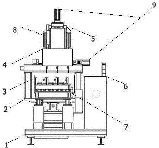
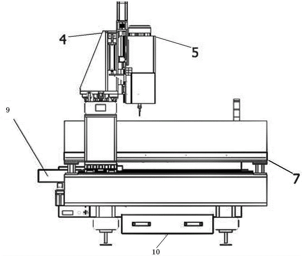
[0037] Such as figure 1 , 2A three-axis multi-head gantry processing equipment is shown, including: machine bed 1, mobile gantry frame 2, compact modular fixture 3, Z-direction feed moving head 4, Y-direction feed moving head 5, electric box 6. The working surface of the machine tool 7, the counterweight cylinder 8, the servo motor 9, and the drawer 10;

[0038] The connection relationship of the above-mentioned components is as follows; the machine bed 1 is provided with an X-direction linear guide rail, the mobile gantry 2 is installed on the X-direction linear guide rail, and a machine tool table 7 is arranged above the mobile gantry 2 The compact modular fixture 3 is located on the machine table 7; the mobile gantry 2 is provided with a Y guide rail and a Z guide rail, and the Y feed moving head 5 is installed on the Y guide rail; the Z The feed moving head 4 is installed on the Z guide rail; the electric box 6 provides electric energy for the operation of the equipment;...


PUM


Abstract

The invention discloses three-axis multi-head gantry machining equipment which comprises a machine tool body, a traveller gantry, a compact type modular clamp, a Z-direction feeding moving head and a Y-direction feeding moving head, wherein an X-direction linear guide rail is arranged on the machine tool body; the traveller gantry is arranged on the X-direction linear guide rail; a machine tool table surface is arranged above the traveller gantry; the compact type modular clamp is positioned on the machine tool table surface; a Y-direction guide rail and a Z-direction guide rail are arranged on the traveller gantry; the Y-direction feeding moving head is mounted on the Y-direction guide rail; the Z-direction feeding moving head is arranged on the Z-direction guide rail. According to the equipment, the machining thinking is changed, the machining idea of fixing a profile and moving a machine is adopted, omni-directional synchronous machining is conducted through the moving heads, comprehensive machining is completed through once positioning, the machining precision is high, and the speed is high.

Description

technical field [0001] The invention relates to processing equipment in the field of deep processing of aluminum profiles and the field of door, window and curtain wall processing, in particular to a three-axis multi-head gantry processing equipment that realizes space universal processing. Background technique [0002] At present, in the aluminum profile door and window processing industry, the milling of aluminum profiles is based on a single profile processing as the main processing form. For complex profiles, multiple end faces need to be processed, and the processing is based on fixed equipment and dynamic profiles. Every time the end face of a spatial position is processed, it needs to be taken out from the processing equipment, repositioned to adjust the positioning processing angle, and processed again. The processing operation is complicated and the processing efficiency is low; [0003] Furthermore, due to the particularity of this industry, the precision requireme...

Claims


Application Information

Patent Timeline
Patent Type & Authority Applications(China)
IPC IPC(8): B23C3/00B23Q3/08B23Q5/10B23Q1/01
Inventor 刘海涛夏政董明
Owner TAICANG WEGOMA MACHINERY
Why Eureka
Try Eureka