Powder printer and powder material molding method

A technology for printers and printing consumables, applied in the field of powder printing, can solve the problems of difficult control of workpiece accuracy, low printing speed, and complex structure of powder printers, and achieve the effects of simplifying structure, improving efficiency, and improving simulation.

Active Publication Date: 2017-02-01
GUANGZHOU VIVID PRINT MATERIAL
View PDF7 Cites 0 Cited by
  • Summary
  • Abstract
  • Description
  • Claims
  • Application Information

AI Technical Summary

Problems solved by technology

[0003] At present, when the powder printer is working, the 3D model of the workpiece is first divided into several layers according to a predetermined direction, and each layer forms a pattern with an outer contour, and then the powder in the silo is laid on the printing area layer by layer. After the powder layer is finished, use the printer to print glue on the powder layer according to the pattern corresponding to the layer, repeat such steps, and finally complete the molding of the workpiece; the current powder printers often require printing glue when completing the above actions The printer can move up and down to achieve powder coating and printing of different corresponding layers, which makes the structure of the powder printer more complicated, the accuracy of the workpiece is difficult to control, and the printing speed is low

Method used


Image

  • Powder printer and powder material molding method
  • Powder printer and powder material molding method
  • Powder printer and powder material molding method

Examples


Embodiment Construction

[0039] Below, in conjunction with accompanying drawing and specific embodiment, the present invention is described further:

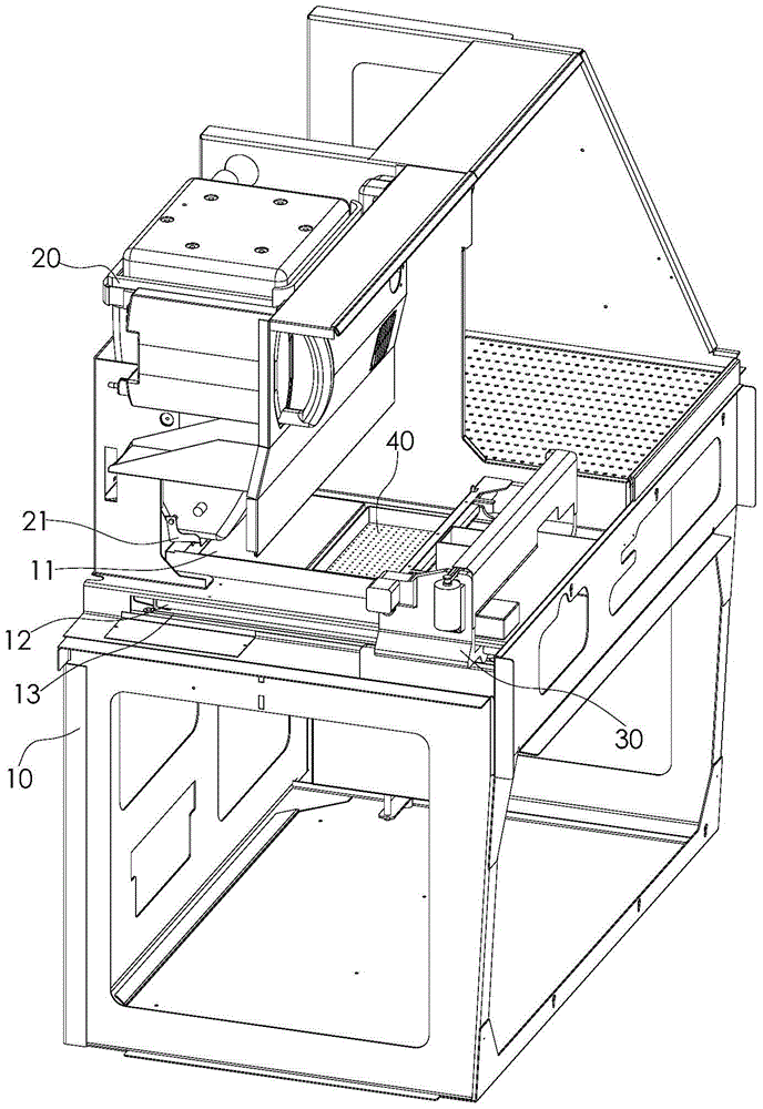
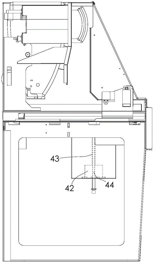
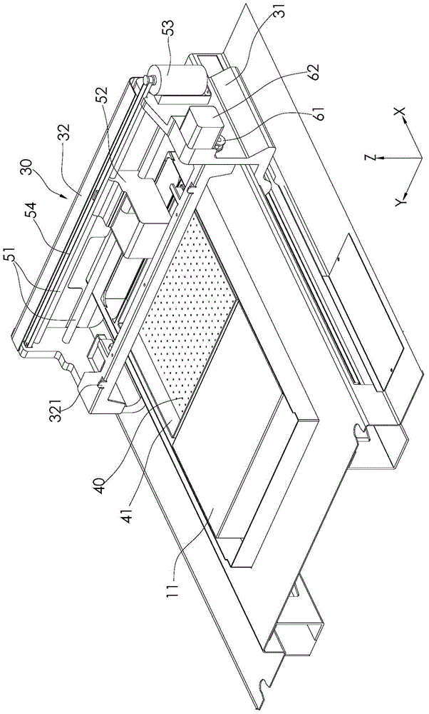
[0040] Such as figure 1 , 2 , shown in 3, is a kind of powder printer of the present invention, and it comprises frame 10, silo 20, printing platform 40, sliding assembly 30, powder spreading roller 61, printer 52, wherein, frame 10 is used as the whole powder printer Foundation, where the X direction in the illustration is the length direction of the frame 10, the Y direction is the width direction of the frame 10, and the Z direction is the height direction of the frame 10. The top of the frame 10 is a working platform. A blanking platform 11 is provided at the rear, and a hollowed out part is provided at the front of the working platform. The hollowed out part and the blanking platform 11 are arranged along the length direction of the frame 10, and the material bin 20 is fixed on the frame through a bracket. 10 and is located above the blanking pla...


PUM

PropertyMeasurementUnit
heightaaaaaaaaaa

Abstract

The invention discloses a powder printer and a powder material molding method. The powder printer comprises a frame, a material bin, a printing platform, a first driving component, a sliding component, a second driving component, a powder spreading roller, a third driving component, a printer and a fourth driving component, wherein an operating platform is arranged on the frame; a blanking platform and a hollow part are arranged on the operating platform; the material bin is fixed on the frame and positioned above the blanking platform; a blanking opening is formed in the lower part of the material bin; the printing platform is embedded into the hollow part; the first driving component is used for driving the printing platform to move in the height direction of the frame; the second driving component is used for driving the sliding component; the powder spreading roller is pivotally connected onto the sliding component; the third driving component is used for driving the powder spreading roller to rotate; the printer is mounted on the sliding component and positioned on the front side of the powder spreading roller; the fourth driving component is used for driving the printer to slide in the width direction of the frame. According to the invention, the stereoscopic formation of workpieces can be implemented, the precision of workpieces can be controlled accurately, the simulation degree of workpieces is improved, besides, the structure of the printer is simplified, and the printing efficiency of workpieces is improved.

Description

technical field [0001] The invention relates to the technical field of powder printing, in particular to a powder printer and a powder material forming method. Background technique [0002] Powder printing is a new type of workpiece forming process. Specifically, powder printing consumables are fixed together in a bonded form using the principle of printing and forming. Compared with traditional mold forming technology, powder printing equipment has low equipment cost. , The high degree of simulation of printed and formed workpieces, etc. Therefore, in the processing of some handicrafts, powder printing technology has been widely used. [0003] At present, when the powder printer is working, the 3D model of the workpiece is first divided into several layers according to a predetermined direction, and each layer forms a pattern with an outer contour, and then the powder in the silo is laid on the printing area layer by layer. After the powder layer is finished, use the print...

Claims


Application Information

Patent Timeline
Patent Type & Authority Patents(China)
IPC IPC(8): B29C67/00
Inventor 刘奎蓝志坚
Owner GUANGZHOU VIVID PRINT MATERIAL
Why Eureka
Try Eureka