Steel pipe discharge mechanism

A technology of unloading mechanism and steel pipe, which is applied in the direction of conveyor objects, transportation and packaging, etc., can solve the problems of heavy workload and poor safety of operators, and achieve the goal of reducing labor intensity, reducing collisions, ensuring the degree of automation and continuous production Effect

Inactive Publication Date: 2014-05-28
陈晓
View PDF0 Cites 6 Cited by
  • Summary
  • Abstract
  • Description
  • Claims
  • Application Information

AI Technical Summary

Problems solved by technology

[0003] Aiming at the disadvantages of heavy workload and poor safety of the operators in the unloading section of the existing steel pipe production, the applicant provides an unloading mechanism for steel pipes that is easy to operate, high in safety, and capable of continuous production

Method used


Image

  • Steel pipe discharge mechanism
  • Steel pipe discharge mechanism

Examples


Embodiment Construction

[0012] The specific implementation manner of the present invention will be described below in conjunction with the accompanying drawings.

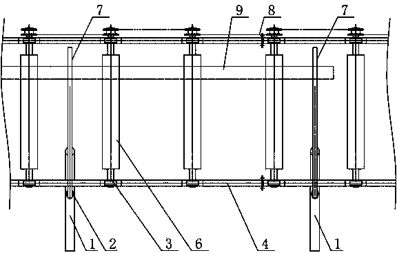
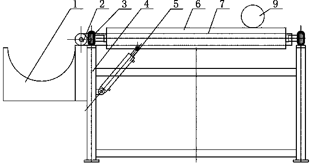
[0013] Such as figure 1 In the unloading section of the steel pipe production line shown, several rollers 6 are supported on the frame 4 of the assembly line by the rollers 3 at both ends to form the main roller table, and are driven and rotated by the traction chain 8 at one end of the rollers 6 to drive the rollers above the rollers 6. Steel pipe 9 is sent forward. Turning plate 7 of the present invention is arranged between two rollers 6, as figure 2 As shown, the flap 7 of the cantilever structure is pivotally installed on the frame 4 through the rotating shaft 2 at one end, and the collecting frame 1 is installed on the outside of the side of the rotating shaft 2 of the frame 4, and the inside is installed with Overturning cylinder 5, one end of overturning cylinder 5 is pivotally connected to frame 4, and the other end is pivotall...


PUM


Abstract

The invention relates to a steel pipe discharge mechanism. A plurality of rollers form a main roller way and are driven to rotate through a drawing chain so as to drive steel pipes on the rollers to be conveyed forwardly; a flap plate is arranged between two rollers, and a rotary shaft at one end of the flap plate is pivotably mounted on a frame; a colleting rack is mounted on the outer side of the frame, the inner side is provided with an overturning cylinder, one end of the overturning cylinder is pivoted to the frame, and the other end is pivoted to the bottom of the flap plate; when the cylinder shrinks in a normal state, the top plane of the flap plate is lower than that of the main roller way. By the aid of the steel pipe discharge mechanism, labor intensity for operators discharging the material among the rollers piece by piece can be reduced greatly, material can be discharged while a pipeline is free of shutdown, production efficiency is improved effectively, and automation degree and continuous production of the pipeline is guaranteed; a soft cushion layer is adopted to reduce collisions between the steel pipes and equipment during discharging, the steel pipes are protected effectively, quality of products is improved, and yield rate of the products is increased.

Description

technical field [0001] The invention relates to the field of steel pipe production line equipment, in particular to a steel pipe unloading mechanism. Background technique [0002] At present, the production line of the steel pipe is manually unloaded in the unloading section, which is not only labor-intensive and the labor rhythm is too tense, there are hidden dangers to personal safety; but also the continuous feeding of the assembly line needs to be suspended, which affects the continuity and automation of production. Contents of the invention [0003] Aiming at the disadvantages of heavy workload and poor safety of operators in the unloading section of the existing steel pipe production, the applicant provides an unloading mechanism for steel pipes that is easy to operate, high in safety, and capable of continuous production. [0004] The technical scheme adopted in the present invention is as follows: [0005] A steel pipe unloading mechanism, a number of rollers form...

Claims


Application Information

Patent Timeline
Patent Type & Authority Applications(China)
IPC IPC(8): B65G47/46
Inventor 陈晓
Owner 陈晓
Why Eureka
Try Eureka