Precast bridge deck space steel pipe concrete truss composite beam and construction method

A technology of steel pipe concrete and steel pipe truss, which is applied in the direction of bridges, bridge parts, bridge construction, etc., and can solve problems such as shortening the construction period, unachievable construction methods, and increasing structural weight

Inactive Publication Date: 2014-05-28
TIANJIN CHENGJIAN UNIV
View PDF5 Cites 18 Cited by
  • Summary
  • Abstract
  • Description
  • Claims
  • Application Information

AI Technical Summary

Problems solved by technology

[0004] In order to shorten the construction period and ensure the construction quality of the bridge deck, the bridge deck can also be poured before installing the steel pipe truss, that is, the bridge deck and the steel pipe truss are dragged or erected together. When this construction method is adopted, the bridge deck will increase the structural weight during installation. For the site where the pier is not high and temporary buttresses can be set up, the steel pipe truss with the bridge deck can be hoisted in sections by a large-tonnage crane; At this time, the weight of the bridge deck will generate a large internal force on the structure when the structure is a large cantilever in the process of dragging and erecting, so that this structural system and construction method cannot be realized, and the only way to erect steel pipe trusses first, and then to construct the bridge deck Construction method

Method used


Image

  • Precast bridge deck space steel pipe concrete truss composite beam and construction method
  • Precast bridge deck space steel pipe concrete truss composite beam and construction method
  • Precast bridge deck space steel pipe concrete truss composite beam and construction method

Examples


Embodiment Construction

[0036] In order to further understand the invention content, characteristics and effects of the present invention, the following examples are given, and detailed descriptions are as follows in conjunction with the accompanying drawings:

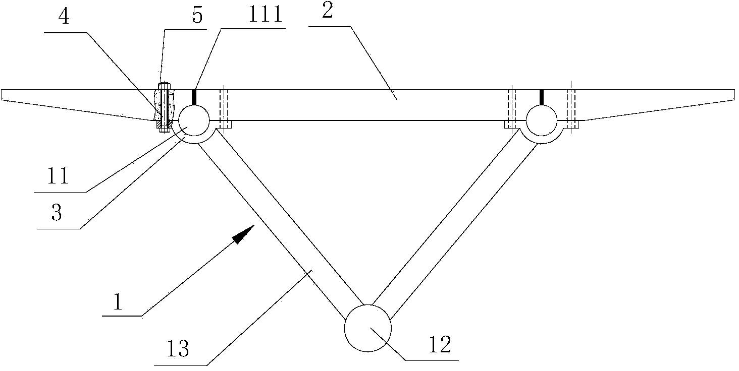
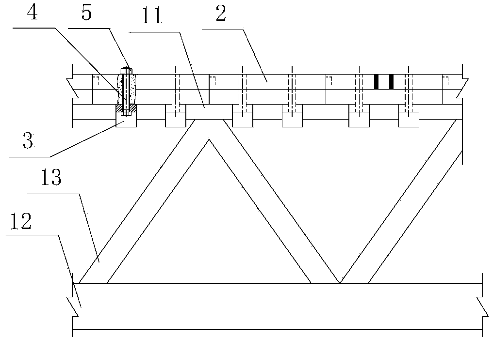
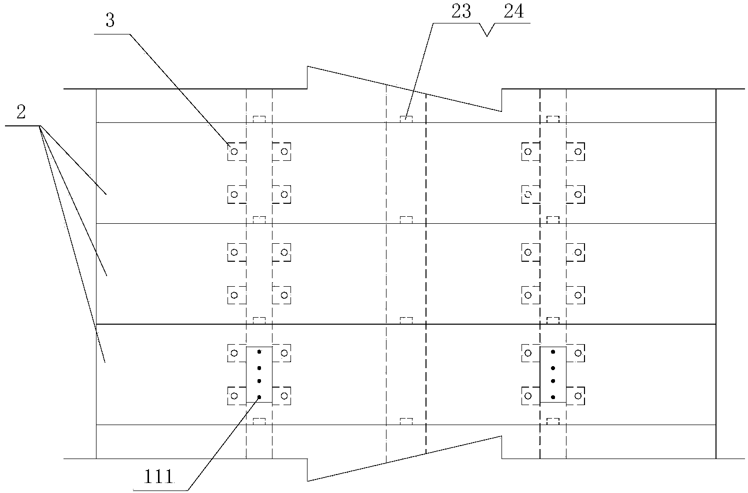
[0037] Prefabricated bridge deck space CFST truss composite beam, please refer to Figure 1-7 . Including the steel pipe truss 1, the steel pipe truss refers to the current technology, which includes two upper chord steel pipes 11, lower chord steel pipes 12 and web bars 13 connecting the upper and lower chord steel pipes. It also includes a plurality of independent bridge decks 2 sequentially laid on the upper part of the steel pipe truss along the longitudinal direction of the bridge. On the lower end surface of each bridge deck, there are two positioning grooves 21 that cooperate with the two upper chord steel pipes of the steel pipe truss one by one, and the upper half of the upper chord steel pipes form an arc surface contact with the p...


PUM


Abstract

A precast bridge deck space steel pipe concrete truss composite beam comprises a steel pipe truss and multiple independent bridge decks; the lower end surface of each bridge deck is provided with two positioning grooves in one-to-one match with two upper chord steel pipes of the steel pipe truss; each upper chord steel pipe is welded with multiple annular lug plates; two end planar parts of each annular lug plate are fixedly connected with the corresponding bridge deck by high-strength bolts. The construction method of the composite beam comprises the steps of precasting the bridge decks; mounting the steel pipe truss; mounting the bridge decks close to the bridge heads; splicing an auxiliary truss on the mounted bridge decks; retreating the auxiliary truss; conveying the bridge decks to be mounted to the front end of the mounted bridge decks and rotating by 90 degrees; forwards moving the auxiliary truss, hoisting the bridge decks to be mounted and forwards pushing to be in-place; pushing for reset and repeating steps 5-7 till all bridge decks are mounted. By adopting the composite beam structure, massive space operation can be avoided, the construction work period is greatly shortened, the cost is reduced, the personal safety in the construction period is ensured and the engineering quality is improved. According to the construction method, the construction difficulty is greatly reduced and the construction period is shortened.

Description

technical field [0001] The invention relates to a space steel pipe concrete truss composite beam, in particular to a prefabricated bridge deck space steel pipe concrete truss composite beam and a construction method thereof. Background technique [0002] In the field of bridge construction technology, the space-filled steel tube concrete truss composite beam is a new type of bridge structure, and bridges of this type have been built, such as the Ganhaizi Super Bridge. The self-weight of this type of bridge is about 50% less than that of a simply supported concrete beam with the same span. While increasing the spanning capacity of the bridge, it can also reduce the amount of engineering work for the lower structure. Therefore, this type of bridge has a good development prospect. [0003] At present, in the construction of space concrete-filled steel pipe truss composite beams at home and abroad, the steel pipe truss is usually erected by dragging, segmental hoisting and other...

Claims


Application Information

Patent Timeline
Patent Type & Authority Applications(China)
IPC IPC(8): E01D19/12E01D21/00
Inventor 王海良杨新磊任权昌董鹏刘中宪张静段晓霞王博孙炜叶圣平张铎王世广刘二梅王秀媛房春艳
Owner TIANJIN CHENGJIAN UNIV
Why Eureka
Try Eureka