Inclined board sand removing water obtaining device

A technology of water intake device and inclined plate, which is applied in water supply device, drinking water device, building, etc. It can solve the problem of unsatisfactory sand removal effect, affecting the sand output effect of the device, and the difficulty of sand discharge through the dual-purpose hole for water inlet and sand discharge, etc. problem, to achieve the long-lasting and stable normal water intake function, reduce the workload of sand removal, and improve the effect of sand removal and water intake

Active Publication Date: 2014-05-28
CHONGQING TECH & BUSINESS INST
View PDF6 Cites 4 Cited by
  • Summary
  • Abstract
  • Description
  • Claims
  • Application Information

AI Technical Summary

Problems solved by technology

[0006] 1. The resistance to water intake is large, resulting in high energy consumption
The device takes water into the device from a number of water inlet and sand discharge holes on the surface of the water inlet chamber, and there is a relatively large water intake resistance, and in the process of water intake, more energy is consumed due to overcoming the greater resistance. Therefore increased energy consumption
At the same time, a deflector is installed at the front end of the sediment separation and self-cleaning chamber of the device, which blocks the water flow, also increases the resistance of the water flow, and further increases the energy consumption when taking water
[0007] 2. The function of water intake is unstable
After long-term use, some water inlet and sand discharge holes on the surface of the device are easily blocked by silt or formed moss, which hinders the water flow function of the water inlet and sand discharge holes. Sometimes it even makes it difficult for the water inlet chamber to enter the water and lose the function of water intake
[0008] 3. The sand removal effect is still not ideal
The water inlet and sand discharge holes provided on the surface of the water inlet chamber of the device actually only allow water to enter through the water inlet and sand discharge holes when the water intake process is started, and it is difficult for sand to flow from the water inlet under its own gravity. The water inlet and sand discharge hole in the lower part of the chamber falls out, so the water inlet and sand discharge hole is difficult to play the role of sand discharge
In addition, the bottom of the sediment separation and self-cleaning room is equipped with multiple self-cleaning and sand-discharging buckets from front to back. It falls into the self-cleaning sand bucket located at the front end of the bottom of the sediment separation and self-cleaning room, so the task of the self-cleaning sand bucket is the heaviest, and because the lower end of the self-cleaning sand bucket is also equipped with a Sand discharge pipe with anti-suckback function. Although the sand discharge pipe has anti-suckback function, it also limits the amount of sand discharged and affects the efficiency of sand discharge.
Therefore, the self-cleaning sand discharge bucket located at the front end of the bottom of the sediment separation and self-cleaning room has heavy sand discharge tasks and low sand discharge efficiency, which is likely to cause the self-cleaning sand discharge bucket to be blocked by sand, thereby affecting the The sand effect of the device

Method used


Image

  • Inclined board sand removing water obtaining device
  • Inclined board sand removing water obtaining device
  • Inclined board sand removing water obtaining device

Examples


Embodiment Construction

[0034] The present invention will be further described in detail below in conjunction with the accompanying drawings.

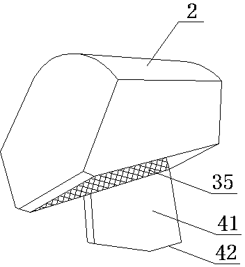
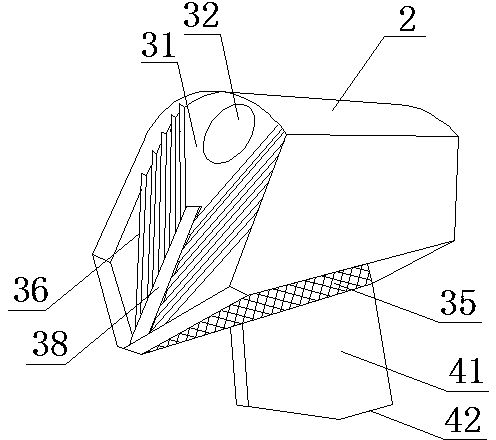
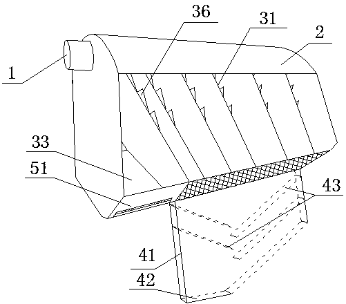
[0035] During specific implementation: if Figure 1 to Figure 7 As shown, a sloping plate desanding and water intake device includes a water outlet pipe 1 and a strip-shaped housing 2 as a whole. The water outlet pipe 1 is fixed at one end of the housing 2 and connected to the housing 2 Connected; also includes an inclined plate sand removal mechanism, the inclined plate sand removal mechanism includes a plurality of inclined plates 31 fixedly arranged in the housing 2 and arranged at intervals along the length direction of the housing 2, wherein each inclined plate The upper end of the plate 31 is inclined to the side of the water outlet pipe 1, and the upper part of each inclined plate 31 is provided with a water hole 32; the inclined plate sand removal mechanism also includes a water outlet chamber 33 and a sand removal and water intake chamber; the housin...


PUM


Abstract

The invention discloses an inclined board sand removing water obtaining device. The inclined board sand removing water obtaining device comprises a water outlet pipe and a shell, wherein the whole shell is of a strip shape. The water outlet pipe is fixedly arranged at one end of the shell. The inclined board sand removing water obtaining device is characterized in that the device further comprises an inclined board sand removing mechanism, the inclined board sand removing mechanism comprises multiple inclined boards fixedly arranged in the shell and arranged at intervals in the length direction of the shell, and the upper portion of each inclined board is provided with a water passing hole; the inclined board sand removing mechanism further comprises a water outlet chamber and a sand removing water obtaining chamber; the water outlet chamber is formed between the end, where the water outlet pipe is located, of the shell and the adjacent inclined board; the sand removing water obtaining chamber is formed between the other end of the shell and the adjacent inclined board; the bottom, where the sand removing water obtaining chamber is located, of the shell is provided with two slopes in the length direction, the inner ends of the two slopes face downwards and are adjacent, a sand discharging groove is formed, and each slope is provided with a filter screen structure used for water inflow. The inclined board sand removing water obtaining device has the advantages of being simple in structure, stable in water obtaining function, small in water obtaining resistance, good in sand removing effect, capable of improving the sand removing water obtaining efficiency and suitable for production, popularization and application.

Description

technical field [0001] The invention belongs to the field of water intake devices, and in particular relates to an inclined plate desand removal device for water intake. [0002] Background technique [0003] In the water intake link with rivers and lakes as the water source, the water intake device installed at the front end of the water pump suction port (the direction of water flow into the front, the same below) is a very critical component, which directly affects the quality of water intake and the safety and stability of water use equipment. [0004] In recent years, due to serious ecological damage, abnormal climate, frequent floods, serious soil erosion and other factors, in rivers and lakes, especially in some mountainous rivers, a large amount of sediment, straw, household garbage and other floating objects are brought into the river during the flood season. . The water intake device that generally adopts at present mainly contains: trumpet type water intake devi...

Claims


Application Information

Patent Timeline
Patent Type & Authority Applications(China)
IPC IPC(8): E03B3/04
Inventor 张伟
Owner CHONGQING TECH & BUSINESS INST
Why Eureka
Try Eureka