
A secondary well formation method for energy storage wells in aquifers

An aquifer and energy storage technology, applied in wellbore/well components, drilling equipment and methods, drilling equipment, etc., can solve the problems of heat loss, insufficient strength, resistance to the promotion of aquifer energy storage technology, etc., to improve the use of Longevity, effect of generating heat loss

Active Publication Date: 2021-10-29
F&S CLEANTECH
View PDF8 Cites 0 Cited by
  • Summary
  • Abstract
  • Description
  • Claims
  • Application Information

AI Technical Summary

Problems solved by technology

However, the energy storage wells in aquifers should avoid metal conduction loss of heat or cooling, and at the same time, in order to avoid metal substances such as rust from causing damage to heat exchangers, heat pumps and other equipment along with the water circulation, the well pipes used are made of PVC, and the connection method It is adhesive type, and its strength and rigidity are far inferior to steel well pipes. In order to reduce the sand content of pumped groundwater, aquifer energy storage wells need to be backfilled with smaller filter material particles, but the smaller the particles, the more difficult it is to clean the well. If you want to achieve the same quality of well washing as the large particle filter material, you need to use a stronger piston to wash the well, which is unbearable for the well pipe made of PVC material
If a powerful piston is used to wash the well, the probability of PVC well wall pipe rupture is extremely high, while other well washing methods cannot completely eliminate the mud wall, which not only limits the water pumping and recharging of the aquifer energy storage well, but also affects the operation of the entire system efficiency, which has caused great resistance to the promotion of aquifer energy storage technology in various geological conditions across the country

Method used


Image

  • A secondary well formation method for energy storage wells in aquifers
  • A secondary well formation method for energy storage wells in aquifers
  • A secondary well formation method for energy storage wells in aquifers

Examples


Embodiment

[0034] Example: Well completion method test for an energy storage well project

[0035]The groundwater type of the proposed site is pore water in the Quaternary loose accumulation layer, and the lithology of the aquifer is mainly round boulders, with strong water permeability and water richness. According to the data in this area, the average permeability coefficient K of the pebble layer is about 80m / d, and the water inflow of a single well is about 50m3 / h. According to the geological characteristics of the site: the main aquifer is round gravel, the maximum particle size is 80mm, and rocks have been seen at about 10 meters. Combined with economic factors, it is known that both positive circulation and reverse circulation are not suitable for energy storage wells in this site Drilling, so the energy storage well drilling method is chosen as percussion drilling.

[0036] 1. Using the traditional one-time well-forming method, after the completion of the well, the energy storag...


PUM


Abstract

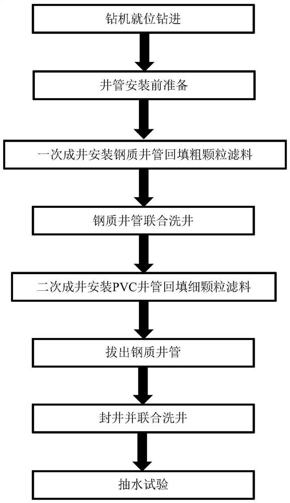
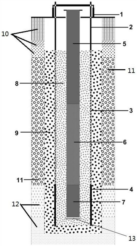
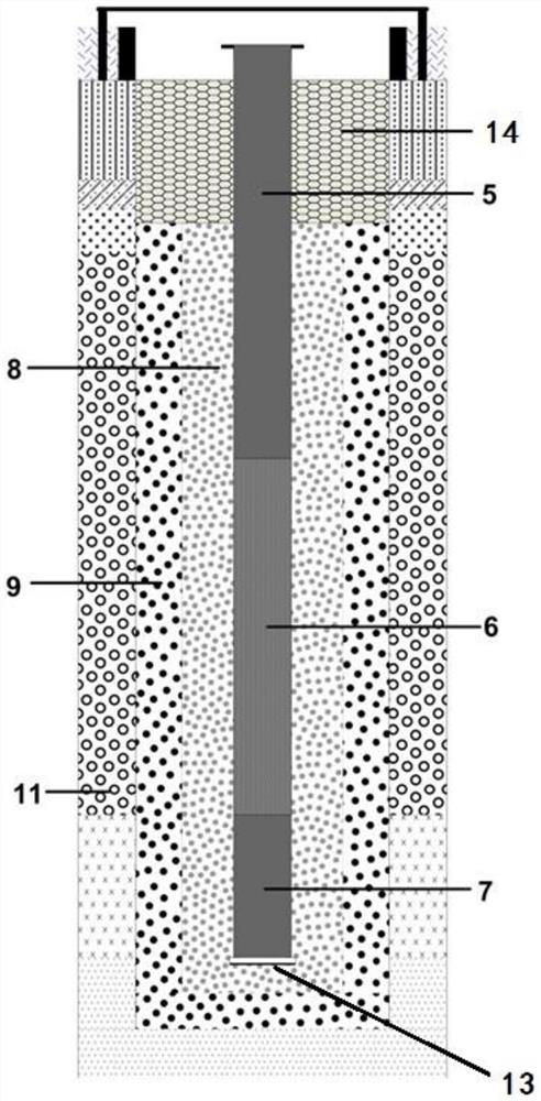
The invention relates to a secondary well-forming method for an aquifer energy storage well, which comprises the following steps: drilling in place with a drilling rig and preparation before well pipe installation, installing steel well pipe backfill filter material for primary well formation, and combined cleaning of steel well pipes. Wells and secondary wells are installed with PVC well pipe backfill filter material, steel well pipes are pulled out, wells are sealed and combined with well washing, and pumping tests are put into use after all parameters are qualified. The secondary well formation equipment includes pipe pullers, Steel well pipe and PVC well pipe. By adopting the secondary well-forming method of the present invention, the steel well pipe and coarse particle filter material can be installed first, and after the first well formation, a relatively strong well washing is carried out, and then the PVC well pipe and fine particle filter material are inserted, and then the steel well is pulled out Pipe, and then use lighter strength to wash the well, which not only solves the problem of excessive mud skin on the well wall caused by the percussion drilling process, but also protects the PVC well pipe, improves the quality of groundwater pumped out of the aquifer energy storage well, and solves the problem of Problems in constructing aquifer energy storage wells in pebble gravel and boulder-bearing formations.

Description

technical field [0001] The invention relates to the field of hydrogeological drilling, in particular to a secondary well-forming method for an aquifer energy storage well. Background technique [0002] In recent years, aquifer energy storage technology has been developed rapidly. At present, the characteristics of aquifers can be fully utilized, heat energy can be stored in summer for use in winter, and cold energy can be stored in winter for use in summer. However, an important prerequisite for this technology is 100% recharge of groundwater raw water, which has higher requirements for the well formation technology of energy storage wells. [0003] A successful well drilling process is divided into two steps, namely drilling and well completion. At present, the drilling technology for ordinary wells is relatively mature, and the gas lift reverse circulation drilling technology is usually used, but this drilling method cannot be applied to formations containing pebbles and ...

Claims


Application Information

Patent Timeline
Patent Type & Authority Patents(China)
IPC IPC(8): E21B37/00E21B37/06E21B7/20E21B41/00E21B43/08E21B43/12E21B47/00
CPCE21B7/20E21B37/00E21B37/06E21B41/00E21B43/08E21B43/121E21B47/00
Inventor 杜刚万军欧阳鑫南
Owner F&S CLEANTECH
Learn More