Fuel activation device

A technology of fuel oil and oil flow, applied in the direction of internal combustion piston engine, charging system, combustion engine, etc., to achieve the effect of improving activity, enhancing change, enhancing activity and kinetic energy

Active Publication Date: 2014-05-28
HUNAN JINANCHANG TECH
View PDF6 Cites 7 Cited by
  • Summary
  • Abstract
  • Description
  • Claims
  • Application Information

AI Technical Summary

Problems solved by technology

[0003]1. The gradient magnetic field composed of multiple layers (at least two layers) of magnetic energy radiation area can carry out multi-stage magnetization sequentially, but because the uniform magnets formed by uniform magnets The magnetic field has a single effect, and the uniform magnetic field has limited activation of the enhanced fuel
[0004]2. Since the permanent magnets are respectively installed in the grooves of the lower support plate, there is a risk of dislocation and movement of the permanent magnets along the grooves due to high pressure during operation , and the installation and disassembly operations of some permanent magnets during assembly or maintenance are more cumbersome

Method used


Image

  • Fuel activation device
  • Fuel activation device
  • Fuel activation device

Examples


Embodiment Construction

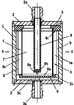
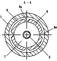
[0035] The inner cavity of the permanent magnet cylinder 4 is an oil flow area 7 .

[0036]The first end cover 2 is connected with a jet tube 8, the jet tube 8 communicates with the oil inlet joint 2a, the jet tube 8 is located in the oil flow area 7, and the inner end of the jet tube 8 is provided with an end plate 8a to form a closed structure, the connection between the end plate 8a and the inner end of the jet tube 8 can be welded or threaded; the tube wall at the inner end of the jet tube 8 is provided with some jet holes 8b communicating with the oil flow area 7, and the jet holes 8b are preferably It is located in the strongest area of ​​the gradient magnetic field of the permanent magnet cylinder 4 . There are various structural forms of the jet hole 8b, which can be a circular hole, a tapered hole, or a slot-shaped hole, etc.; when the jet hole 8b is a tapered hole, it can be an inner tapered or outer tapered structure; When the jet hole 8b is a circular hole or a sl...


PUM


Abstract

Disclosed is a fuel activation device. A fuel inlet joint is formed in a first end cover (2) at one end of a shell body (1), an oil outlet joint is formed in a second end cover (3) at the other end of the shell body (1), a sealing ring (5) is arranged at the upper end of a permanent magnet cylinder (4) inside the shell body, a sealing plate (6) is arranged at the lower end of the permanent magnet cylinder (4) inside the shell body, a jet pipe (8) connected to the first end cover (2) is arranged in a fuel flow area (7), a plurality of jet flow holes (8b) are formed in the end in the jet pipe, and a fuel flow channel (9) is formed between the outer wall face of the permanent magnet cylinder and the inner wall face of the shell body. A plurality of V-shaped grooves (4a) are formed in the wall of the permanent magnet cylinder, a first groove (3b) matched with the sealing plate (6) is formed in the inner wall face of the second end cover, and a radial fuel channel (3c) communicated with the fuel flow channel (9) is formed in the wall body. The magnetic field intensity of the permanent magnet cylinder (4) is the intensity of a gradient magnetic field which is changed in a gradient mode along the axis of the permanent magnet cylinder. The fuel activation device has the advantages of improving the fuel magnetization effect, enhancing the activation and kinetic energy of the fuel, saving the fuel, reducing pollutants in exhausted gas and the like.

Description

Technical field: [0001] The patent of the present invention relates to a fuel activation device, in particular to a fuel activation device that activates fuel molecules and enhances fuel kinetic energy through the action of a magnetic field. Background technique [0002] The invention patent document of application number 201010225778.4 discloses a "vehicle fuel saving device". It discloses a "fuel magnetization processor", its structure includes a housing, one end of the housing is connected to an end cover with an oil inlet joint, one end of the housing is connected to an end cover with an oil outlet joint, and the housing is equipped with a The two magnetized areas in series form are called the gradient magnetic field magnetic energy radiation area, and there are independent permanent magnets uniformly distributed along the circumferential direction in the magnetized area, and the central cavity between two adjacent permanent magnets and the magnetized area is the magneti...

Claims


Application Information

Patent Timeline
Patent Type & Authority Applications(China)
IPC IPC(8): F02M27/04
CPCY02T10/12
Inventor 葛凌志肖云华
Owner HUNAN JINANCHANG TECH
Why Eureka
Try Eureka