fuel activation device

A technology of fuel oil and oil flow, applied to internal combustion piston engines, charging systems, combustion engines, etc., can solve the problems of cumbersome installation and disassembly operations, limited activation of fuel oil, and dislocation and movement of permanent magnets, so as to improve the activation effect and improve Magnetization effect, enhanced effect of change

Active Publication Date: 2016-08-17
HUNAN JINANCHANG TECH
View PDF6 Cites 2 Cited by
  • Summary
  • Abstract
  • Description
  • Claims
  • Application Information

AI Technical Summary

Problems solved by technology

[0003]1. The gradient magnetic field composed of multiple layers (at least two layers) of magnetic energy radiation area can carry out multi-stage magnetization sequentially, but because the uniform magnets formed by uniform magnets The magnetic field has a single effect, and the uniform magnetic field has limited activation of the enhanced fuel
[0004]2. Since the permanent magnets are respectively installed in the grooves of the lower support plate, there is a risk of dislocation and movement of the permanent magnets along the grooves due to high pressure during operation , and the installation and disassembly operations of some permanent magnets during assembly or maintenance are more cumbersome

Method used


Image

  • fuel activation device
  • fuel activation device
  • fuel activation device

Examples


Embodiment Construction

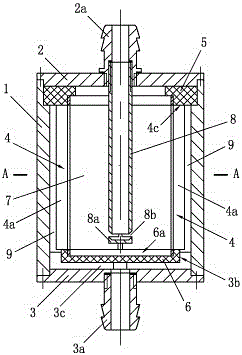
[0034] It includes a housing 1, one end of the housing is connected to the first end cover 2, the first end cover 2 is provided with an oil inlet joint 2a, the other end of the housing is connected to the second end cover 3, and the second end cover 3 is provided with an oil outlet Connector 3a, see figure 1 ; During implementation, the housing and end caps should avoid materials that affect the magnetic field.

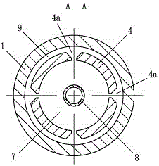
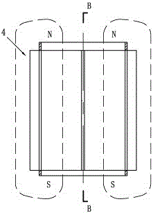
[0035] A permanent magnet cylinder 4 is arranged in the housing 1, such as figure 1 , Figure 3 to Figure 5 As shown, the permanent magnet cylinder 4 is an integral structure, the upper end of the permanent magnet cylinder 4 is provided with a seal ring 5, and the seal ring 5 cooperates with the first end cover 2 and the inner wall surface of the housing 1 to form a sealing structure. The permanent magnet cylinder 4 The lower end is provided with a sealing plate 6, which constitutes the sealing structure of the lower port of the permanent magnet cylinder 4, see ...


PUM


Abstract

Fuel activation device. There is an oil inlet joint on the first end cover (2) at one end of the housing (1), and an oil outlet joint on the second end cover (3) at the other end; a sealing ring ( 5), the lower end is provided with a sealing plate (6); the jet tube (8) connected to the first end cover (2) is located in the oil flow area (7), and there are several jet holes (8b) at the inner end of the jet tube; the permanent magnet cylinder There is an oil flow channel (9) between the outer wall of the body and the inner wall of the housing; there are several V-shaped grooves (4a) on the wall of the permanent magnet cylinder; the inner wall of the second end cover is provided with the seal The first groove (3b) matched with the plate (6) has a radial oil channel (3c) in the wall that communicates with the oil flow channel (9); the magnetic field strength of the permanent magnet cylinder (4) is A gradient magnetic field with a gradient change. It has the characteristics of improving the magnetization effect of fuel, enhancing the activity and kinetic energy of fuel, saving fuel and reducing pollutants in exhaust gas.

Description

Technical field: [0001] The patent of the present invention relates to a fuel activation device, in particular to a fuel activation device that activates fuel molecules and enhances fuel kinetic energy through the action of a magnetic field. Background technique [0002] The invention patent document of application number 201010225778.4 discloses a "vehicle fuel saving device". It discloses a "fuel magnetization processor", its structure includes a housing, one end of the housing is connected to an end cover with an oil inlet joint, one end of the housing is connected to an end cover with an oil outlet joint, and the housing is equipped with a The two magnetized areas in series form are called the gradient magnetic field magnetic energy radiation area, and there are independent permanent magnets uniformly distributed along the circumferential direction in the magnetized area, and the central cavity between two adjacent permanent magnets and the magnetized area is the magneti...

Claims


Application Information

Patent Timeline
IPC IPC(8): F02M27/04
CPCY02T10/12
Inventor 葛凌志肖云华
Owner HUNAN JINANCHANG TECH
Why Eureka
Try Eureka