Radial attachment and positioning flanges for axial turbomachine casing sections

An axial-flow turbine and turbine technology, applied in the field of fixed brackets, axial-flow turbines, and adjoining casings, can solve problems such as increasing the flange radius, reduce radial size, achieve compactness and precision, The effect of simple machining process

Inactive Publication Date: 2014-05-28
SAFRAN AERO BOOSTERS SA
View PDF8 Cites 1 Cited by
  • Summary
  • Abstract
  • Description
  • Claims
  • Application Information

AI Technical Summary

Problems solved by technology

However, it requires a cylindrical section at the top of one of the flanges, thereby increasing the radius of the flange

Method used


Image

  • Radial attachment and positioning flanges for axial turbomachine casing sections
  • Radial attachment and positioning flanges for axial turbomachine casing sections
  • Radial attachment and positioning flanges for axial turbomachine casing sections

Examples


Embodiment Construction

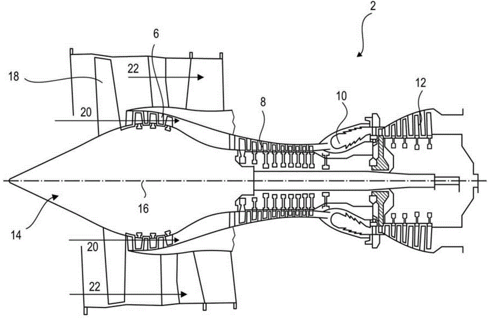
[0047] In the following description, the terms inner and outer refer to the position relative to the axis of rotation of the axial turbine.

[0048] figure 1 The axial turbine is shown. In this case, it is a dual-flow turbojet. The turbojet 2 includes a first compression stage (so-called low-pressure compressor 6), a second compression stage (so-called high-pressure compressor 8), a combustion chamber 10 and one or more turbine stages 12. In operation, the mechanical power of the turbine 12 is transmitted to the rotor 14 through the central shaft, driving the two compressors 6 and 8. A reduction mechanism can increase the rotational speed transmitted to the compressor. Alternatively, each of the different turbine stages may be connected to the compressor stage by a concentric shaft. These concentric shafts include several rotor blade rows, which are associated with stator blade rows. The rotation of the rotor about its axis of rotation 16 generates an air flow, and gradually ...


PUM


Abstract

An axial turbomachine housing (2) is designed to channel a primary annular flow in the low-pressure compressor of the turbomachine. The housing has a first shell (32, 132) and a second shell (34, 134) designed to be contiguous and coaxial. The first shell (32, 132) has a flange (48, 148) and a centring surface (54, 154) substantially cylindrical. The second shell (34, 134) has a flange and radial centring means (52, 152) designed to mate with the centring surface (54, 154). The flange of the first shell includes cut-outs (58, 158) distributed along its circumference, and the centring means extend axially from the flange of the second shell through the cut-outs to the centring surface where the two flanges are in contact.

Description

Technical field [0001] The present invention relates to the casing of an axial turbine. More specifically, the present invention relates to an adjoining casing in the casing of an axial turbine. More specifically, the present invention relates to a fixed bracket between the casings in the casing of an axial turbine. The invention relates to the concentricity between the two casings of a turbine fixed by radial flanges. The invention also relates to an axial turbine. Background technique [0002] Turbines usually include a plurality of annular passages through which air flows to generate driving force. The air flow passes through the fan, compressor, combustion chamber and turbine. In or between these elements, the casing of the turbine helps direct the air flow by confining the air flow in the turbine itself. [0003] The casing is composed of an annular wall that reacts to changes in the cross-section of the airflow. In this regard, the casing includes a shell having a gener...

Claims


Application Information

Patent Timeline
Patent Type & Authority Applications(China)
IPC IPC(8): F04D29/52
CPCF01D25/243F05D2230/64F05D2260/36Y02T50/60
Inventor C.雷米
Owner SAFRAN AERO BOOSTERS SA
Why Eureka
Try Eureka