
Device and method for detecting vibration performance parameters of a curtain wall panel earthquake simulation system
A technology for earthquake simulation and parameter detection, which is applied in the directions of measuring devices, vibration testing, and testing of machine/structural components, and can solve problems such as insufficient detection accuracy
- Summary
- Abstract
- Description
- Claims
- Application Information
AI Technical Summary
Problems solved by technology
Method used
Image

Examples
Embodiment Construction
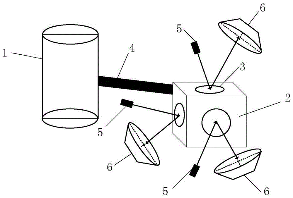
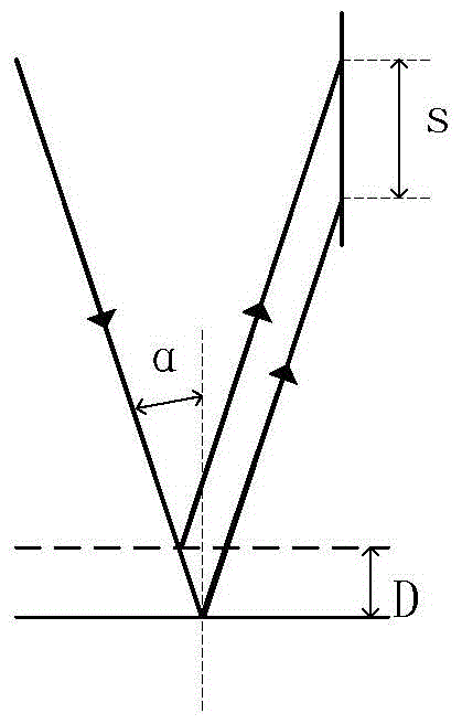
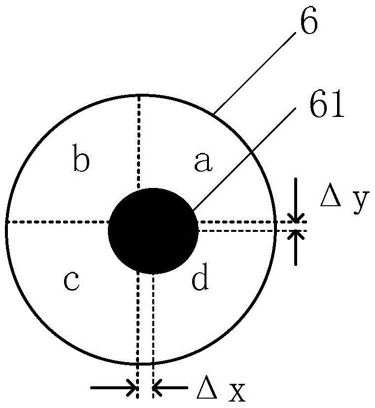
[0043] see Figure 1 ~ Figure 4 , the vibration performance parameter detection device of the curtain wall panel earthquake simulation system of the present invention includes: a vibration table 1 for simulating seismic vibration, in which a motor (not shown) is arranged; a fixed base 2, which is a cube, its Reflectors 3 are respectively arranged on the three surfaces perpendicular to the X-axis, Y-axis and Z-axis respectively, and the fixed base 2 forms a rigid connection with the vibrating table 1 through the connecting rod 4; three laser light sources 5 are respectively arranged on Relatively above each reflector 3; the angle between the laser light emitted by the laser light source 5 and the normal line of the reflector 3 is 8-12°; three four-quadrant laser detectors 6 are respectively arranged on each reflector 3; opposite to the laser light source 5, the angle between the four-quadrant laser detector 6 and the normal line of the reflector 3 is less than or equal to 45°; ...
PUM
 Abstract
Description
Claims
Application Information