Automatic fire-extinguishing patch board

A technology of automatic fire extinguishing and plug-in boards, which is applied in the direction of electrical components, coupling devices, circuits, etc., can solve the problems of low safety and achieve the effects of high safety, simple structure and convenient installation

Inactive Publication Date: 2014-05-28
鄄城长青生物质能源有限公司
View PDF6 Cites 8 Cited by
  • Summary
  • Abstract
  • Description
  • Claims
  • Application Information

AI Technical Summary

Problems solved by technology

Its main body is not much different from the existing plug-in board, except that it has more timing and photometric control functions, and its safety is still as low as that of ordinary plug-in boards.

Method used


Image

  • Automatic fire-extinguishing patch board
  • Automatic fire-extinguishing patch board
  • Automatic fire-extinguishing patch board

Examples


Embodiment 1

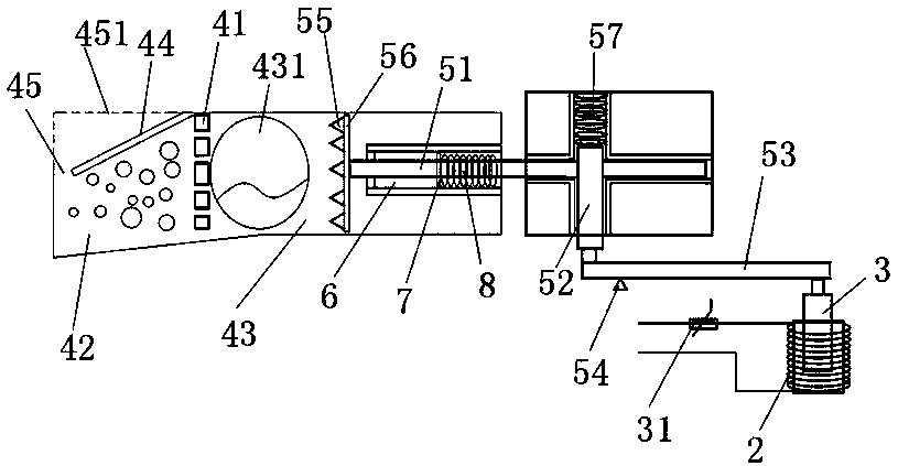
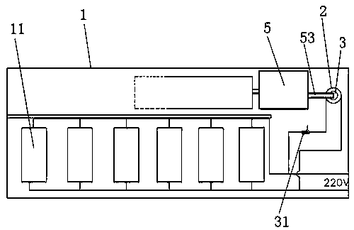
[0039] An automatic fire extinguishing plug board, comprising a plug board housing 1 and a socket 11 arranged in the plug board housing 1, the housing 1 is provided with fire extinguishing equipment, and the fire extinguishing equipment includes a braking device and a reaction device, the reaction device includes a reaction box, and the reaction box is provided with a baffle 41 that separates the reaction box into two communicating areas. Both sides of the baffle 41 are reactant chambers, and the braking device includes A coil 2 connected in parallel to the socket, a negative thermistor 31 connected in series with the coil 2, an iron rod 3 inserted in the coil 2 to move up and down, and a push rod assembly that brakes through the iron rod 3 and extends into the reaction box.

[0040] The stopper 41 is a plurality of stoppers arranged vertically or a partition with through holes, wherein the reactant chamber on the front side of the stopper 41 is a solid reactant chamber 42, an...

Embodiment 2

[0051] The difference from the above embodiment is that the stopper 41 is a plurality of stoppers arranged obliquely and transversely or a partition with through holes, and the reactant cavities on the upper and lower sides of the stopper 41 are liquid storage chambers 43. A liquid storage bag 431 is arranged in the liquid bag cavity 43 , and a bag pressing part is arranged at the front end of the push rod assembly. A limit projection is arranged on the lower surface of the stopper to ensure that the lower fluid storage bag will not slide forward.

[0052] The reactants can be two kinds of liquids arranged up and down, that is, a liquid compound for reaction is stored in each liquid storage bag, and the liquid storage bag is punctured by the bag-punching part, and the liquid in the upper liquid storage bag passes through the gap between the stoppers. The through holes in the gap or partition flow down and mix with the reaction liquid located in the lower part, thereby producin...


PUM


Abstract

The invention belongs to the field of patch boards, and particularly relates to an automatic fire-extinguishing patch board. The automatic fire-extinguishing patch board comprises a patch board shell and sockets in the patch board shell, wherein fire-extinguishing equipment is arranged in the shell and consists of a braking device and a reaction device, the reaction device comprises a reaction box, a stopper is arranged in the reaction box, reactant cavities are formed in two sides of the stopper, the braking device comprises a coil, a negative thermistor, an iron rod and a push rod assembly, the coil is connected with the sockets in parallel through a wire, the negative thermistor is connected in series with the coil, the iron rod is inserted in the coil and can move up and down, and the push rod assembly is braked by the iron rod and extends in the reaction box. The patch board is improved according to the chemical principle that carbon dioxide has no combustion-supporting function, and when the patch board catches fire due to short circuit and the like in the use process, a sensor inside the patch board can detect the fire, the fire-extinguishing equipment is started, the carbon dioxide generation device fast generates and emits carbon dioxide, and an oxygen-free environment is formed around a fire source to achieve the fire extinguishment effect.

Description

technical field [0001] The invention belongs to the field of plug-in boards, and in particular relates to an automatic fire-extinguishing plug-in board. Background technique [0002] According to social surveys, since the 1990s, the number of fires caused by electrical failures, casualties, and direct property losses have remained high in China. Among them, the accidents caused by the fire problem of the plug board accounted for the majority. Plug-in boards are widely used in household life and industrial production, but existing plug-in boards cannot extinguish themselves when a fire breaks out, so there is a great potential safety hazard. The plug boards on the market do not have automatic fire extinguishing function. For example, a plug-in board disclosed with the application number "201310143700.1" relates to the structural connection of the built-in electrical components, mainly including the plug-in board body and the control circuit, wherein the plug-in board shell ...

Claims


Application Information

Patent Timeline
Patent Type & Authority Applications(China)
IPC IPC(8): H01R13/527H01R13/66
Inventor 沈佳晨陈邢凯马萍
Owner 鄄城长青生物质能源有限公司
Why Eureka
Try Eureka