Electric energy multiplication device named 'electric multiplication motor'

A technology of electric energy and electric energy conversion, applied in electromechanical devices, control mechanical energy, electrical components, etc., can solve problems such as electromechanical products that have not yet been seen, and achieve the effect of reducing quality and eliminating frictional resistance

Inactive Publication Date: 2014-05-28
罗招全
View PDF0 Cites 3 Cited by
  • Summary
  • Abstract
  • Description
  • Claims
  • Application Information

AI Technical Summary

Problems solved by technology

So far, no electromechanical products for the purpose of increasing electric energy have been seen

Method used


Image

  • Electric energy multiplication device named 'electric multiplication motor'
  • Electric energy multiplication device named 'electric multiplication motor'
  • Electric energy multiplication device named 'electric multiplication motor'

Examples


Embodiment 1

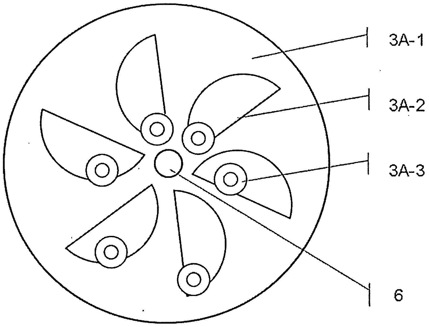
[0080] a kind of like Figure 16 The power multiplication device named "motor booster" shown includes electric unit 1, power generation unit 2, flywheel 3A, control system 4, power conversion device 5, stationary shaft 6, bearing 7, fan 8, frame 9, end The cover 10, the base 11, and the cooling rib 12 are characterized in that:

[0081] (1) The "motor booster" is a horizontal concentric structure, and its essence is to nest the smaller outer rotor permanent magnet motor 1 and the larger inner rotor permanent magnet generator 2 together, The permanent magnet rotor 2-2 of the power generation unit is suspended outside the permanent magnet rotor 1-2 of the electric unit and can rotate accordingly under the action of magnetic force;

[0082] (2) The stator 1-1 of the electric unit is composed of iron core, winding, insulating lining, and junction box. Winding on the slot teeth where the insulating lining is laid, or the winding coil can be wound first and then embedded in the wi...

Embodiment 2

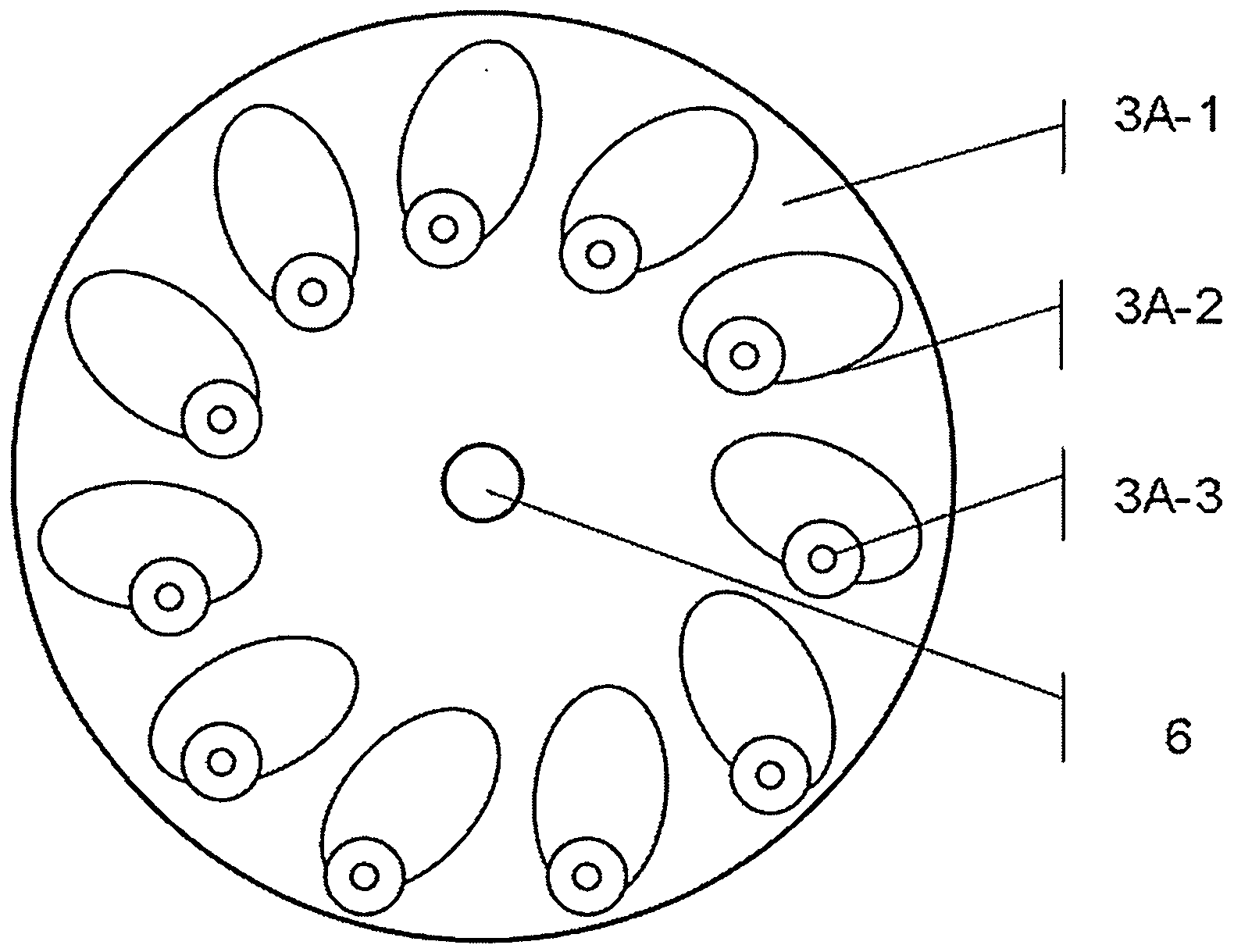
[0091] a kind of like Figure 16 The power multiplication device named "motor booster" shown includes electric unit 1, power generation unit 2, flywheel 3A, control system 4, power conversion device 5, stationary shaft 6, bearing 7, fan 8, frame 9, end The cover 10, the feet 11, and the cooling ribs 12 are characterized in that: the arrangement of the permanent magnets of the electric unit rotor and the generator unit rotor is a Halbach array formed by radial, tangential, and obliquely magnetized fan-shaped permanent magnets, and the magnetic energy The reinforced side faces the air gap side outward; the flywheel uses gravity and magnetic force to assist the flywheel. The rest of the implementation details are the same as Example 1.

Embodiment 3

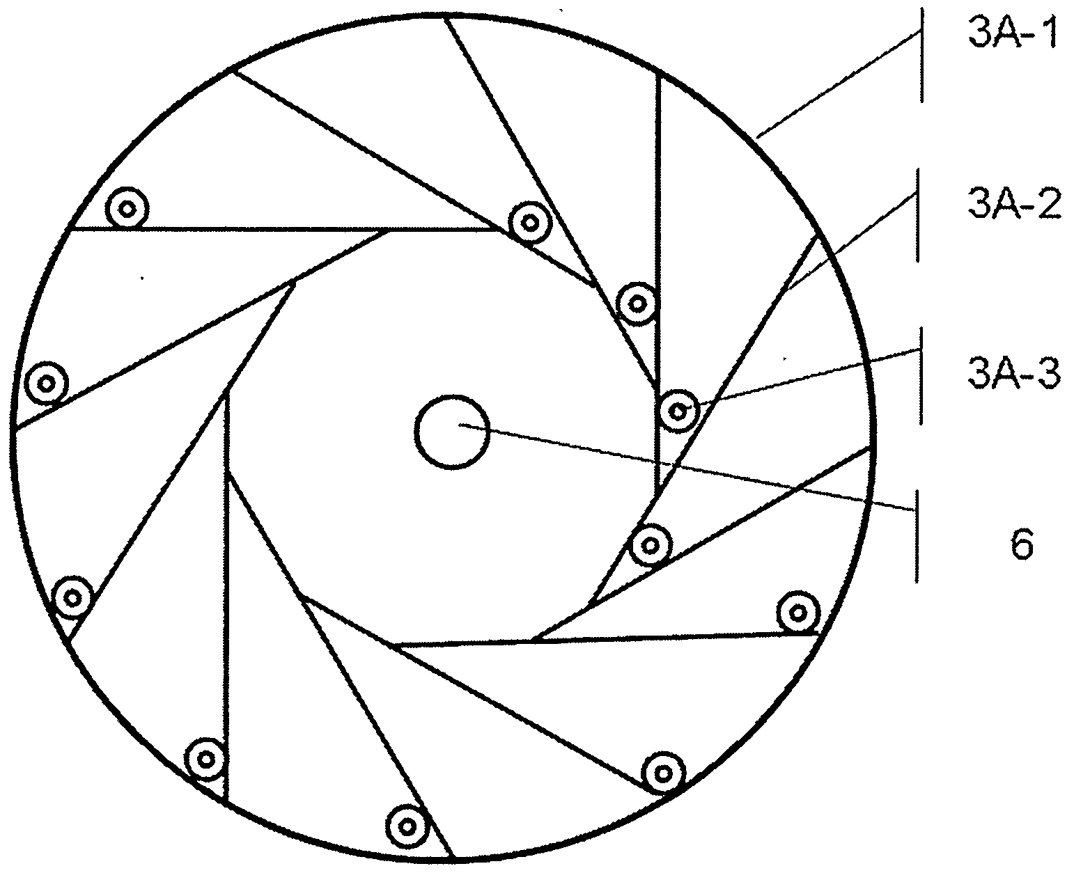
[0093] a kind of like Figure 17 The power multiplication device named "motor booster" shown includes electric unit 1, power generation unit 2, flywheel 3A, control system 4, power conversion device 5, stationary shaft 6, bearing 7, fan 8, frame 9, end The cover 10, the ground feet 11, and the heat dissipation ribs 12 are characterized in that: the rotor 1-2 of the electric unit and the rotor 2-2 of the power generation unit are combined into one, and the inner and outer layers are permanent magnet rotors, that is, on the annular back yoke An annular iron core is arranged, and permanent magnets are respectively arranged on the outer circumference of the annular iron core and the wall of the inner hole. Other than that, other implementation details are the same as those in Example 1.


PUM


Abstract

The invention discloses an electric energy multiplication device named an 'electric multiplication motor'. The electric energy multiplication device comprises an electrically-driven unit, a power-assisted flywheel, an electricity generation unit, a control system and an electric energy conversion device and is characterized in that a motor with low mass is associated with a permanent-magnet generator with high mass, the electrically-driven unit is electrified to drive the flywheel and the electric generation unit to run, and the stator of the electric generation unit is enabled to output electric energy; when the electrically-driven unit is powered off, the rotor of the electrically-driven unit and the rotor of the electric generation unit are capably of continuing to run under the influence of the rotational inertia of the flywheel and a power-assisted mechanism, the stator of the electrically-driven unit and the stator of the electric generation unit are enabled to output electric energy, the electric energy output by the stator of the electrically-driven unit is converted to a self-contained power source by the electric energy conversion device; the electric generation unit is capable of continuously outputting electric energy by periodic switch conversion, thus much electric energy output can be obtained from low electric energy investment. The electric energy multiplication device disclosed by the invention has the functions of charging, electric multiplicatig on and discharging, as well as is capable of being used for electric multiplication and accumulation for families, and capable of being used as a mobile power supply.

Description

【Technical field】 [0001] The invention belongs to the technical field of energy-saving equipment, and in particular relates to an electric energy multiplication device named "motor booster". 【Background technique】 [0002] Since Faraday discovered the phenomenon of electromagnetic induction, people have successively invented generators, motors, condensers, and flywheel energy storage devices. In recent years, dual-rotor motors have appeared. The purpose of the generator is to convert mechanical energy into electrical energy; the purpose of the motor is to convert electrical energy into mechanical energy; The electric energy is converted into the kinetic energy of the flywheel and temporarily stored until the electricity is used, and then the kinetic energy of the flywheel is converted into electric energy. The purpose of the dual-rotor motor is to provide a dual power output window. Their ultimate goal is not the conversion of energy forms, but also the storage and backup o...

Claims


Application Information

Patent Timeline
Patent Type & Authority Applications(China)
IPC IPC(8): H02K53/00H02K7/02
CPCY02E60/16
Inventor 罗招全
Owner 罗招全
Why Eureka
Try Eureka