Roller bearing

一种滚子轴承、滚子的技术,应用在滚子轴承领域,能够解决滚子破损等问题,达到冷却效果提高、实现寿命、长寿命的效果

Active Publication Date: 2014-05-28
NTN CORP
View PDF8 Cites 13 Cited by
  • Summary
  • Abstract
  • Description
  • Claims
  • Application Information

AI Technical Summary

Problems solved by technology

[0019] However, even if the groove 36 is provided on the wall surface of the pocket hole 28 as described above, and the foreign matter and wear powder are collected by the groove 36, the wear powder will still be bitten between the opening end edge of the groove 36 and the roller, and there is The problem of premature roller breakage caused by the ingress of wear powder

Method used


Image

  • Roller bearing
  • Roller bearing
  • Roller bearing

Examples


Embodiment Construction

[0040] based on Figure 1 ~ Figure 4 Embodiments of the present invention will be described.

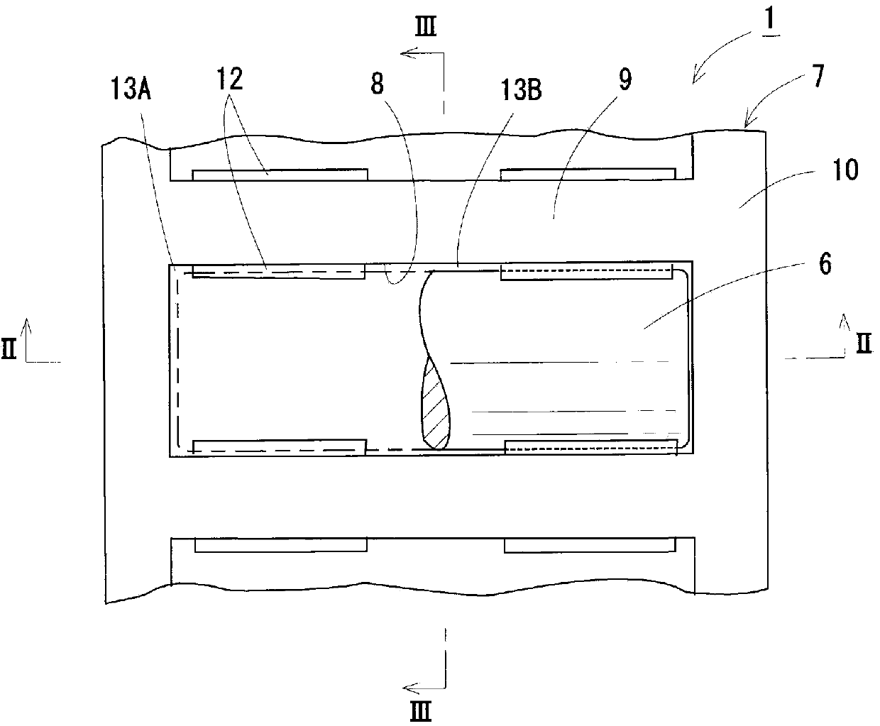
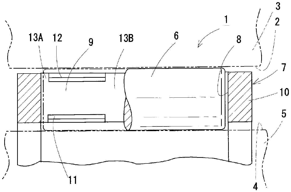
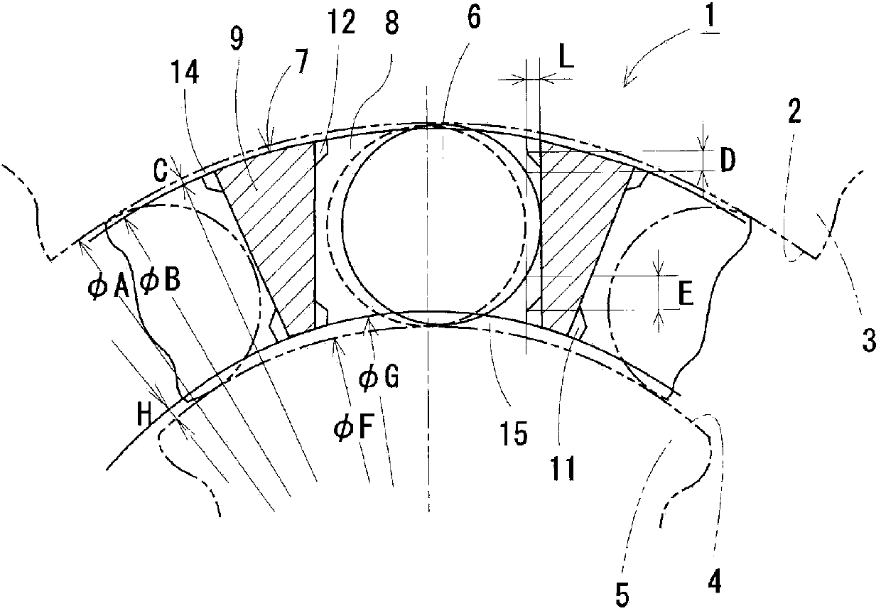
[0041] The roller bearing 1 includes: an outer member 3 having a cylindrical outer raceway 2 on the inner peripheral surface; an inner member 5 having a cylindrical inner raceway 4 on the outer peripheral surface; A plurality of rollers 6 are freely rotatably provided between the inner raceway 4 and the inner raceway 4 .

[0042] The rollers 6 are formed into cylindrical bodies made of a metal material or the like, and are configured in the form of needle rollers, cylindrical rollers, etc., and are regularly arranged and held in a cylindrical cage 7 as a whole.

[0043] The cage 7 has rectangular pockets 8 for regularly accommodating the rollers 6 at predetermined intervals in the circumferential direction, and is formed of a resin material by injection molding or the like. The cage 7 is formed so that the pockets 8 pass through from the inner diameter side to the outer diameter si...


PUM


Abstract

The problem addressed by the present invention is to increase service life by causing surface imprinting or an oil film shortage to not arise at a roller (6) by preventing the pinching and retention of wear debris in the pocket (8) of the holder (7) of a roller bearing (1). In the state of a roller (6) and a holder (7) being combined between an outer member (3) and an inner member (5), lubricating oil is caused to smoothly flow through the gap formed between the outer peripheral surface of the roller (6) and the cylindrical section (9) of the holder (7) by stipulating the position and dimensional relationship of the inner protrusion (11) and outer protrusion (12) of the cylindrical section (9), the diameter of an outer ring raceway (2), the diameter of an inner ring raceway (4), and the inner / outer diameters of the holder (7) in a manner so that the inner protrusion (11); and outer protrusion (12) that are for preventing the dropout of the roller (6) and are provided to the cylindrical section (9) of the holder (7) are constantly not touching the outer peripheral surface of the roller (6).

Description

technical field [0001] The present invention relates to a roller bearing suitable for use in a planetary gear reduction unit. Background technique [0002] Such as Figure 5 ~ Figure 7 As shown, the roller bearing 21 includes: an outer part 23 having a cylindrical outer ring track 22 on the inner peripheral surface; an inner part 25 having a cylindrical inner ring track 24 on the outer peripheral surface; A plurality of rollers 26 are rotatably provided between the ring rail 22 and the inner ring rail 24 . [0003] The roller 26 is rotatably held by a cylindrical cage 27 as a whole. The cage 27 has pockets 28 for accommodating the rollers 26 at predetermined intervals in the circumferential direction, and has column portions 29 between the adjacent pockets 28 in the circumferential direction, and on both sides of the column portion 29 in the axial direction. Ring portion 30 . [0004] The column portion 29 of the cage 27 is provided with an inner protrusion 31 and an oute...

Claims


Application Information

Patent Timeline
Patent Type & Authority Applications(China)
IPC IPC(8): F16C33/46F16C19/26F16C33/56F16C33/66F16H1/28
CPCF16H1/28F16C2240/46F16C33/4635F16C33/6681F16H2057/085F16C33/56F16C33/4629F16C33/4617F16C33/4676F16C19/26F16C33/6651F16C33/4605F16C2361/61F16C33/4623
Inventor 中川勉西村雅大石真司
Owner NTN CORP
Why Eureka
Try Eureka