Railway vehicle body chassis structure

A rail vehicle and underframe technology is applied in the field of high-strength subway vehicles and rail vehicle body underframe structures, and can solve the problem that the distance between the traction guide beam and the coupler mounting hole becomes larger, the end structure of the underframe cannot meet the technical requirements, and the support The effect of weakening the function and other problems can achieve the effect of light weight, high strength performance, and easy modular production

Active Publication Date: 2014-06-04
ZHUZHOU ELECTRIC LOCOMOTIVE CO
View PDF10 Cites 43 Cited by
  • Summary
  • Abstract
  • Description
  • Claims
  • Application Information

AI Technical Summary

Problems solved by technology

However, after the front coupler is adopted, the distance between the coupler mounting holes is narrowed and the vertical plate of the traction beam is required to move accordingly, causing the bogie mounting hole at the bolster to enter the closed area between the vertical plates of the traction beam. There is no room for operation when connecting the bolts of the car body; the distance between the traction guide beam and the coupler installation hole becomes larger, and the supporting effect is weakened; The car seat is set on the board, which interferes with the original jumper box at this position
[0003] Due to the above factors, the existing underframe end structure can no longer meet the relevant technical requirements

Method used


Image

  • Railway vehicle body chassis structure
  • Railway vehicle body chassis structure
  • Railway vehicle body chassis structure

Examples


Embodiment 1

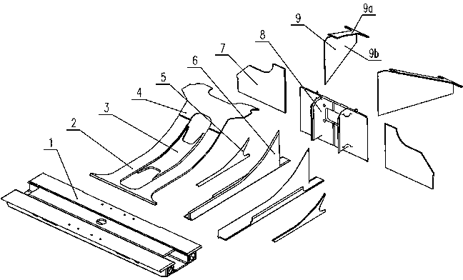
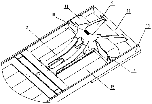
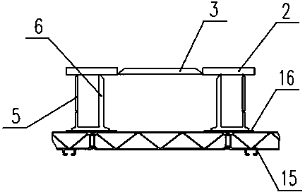
[0031] A subway car body underframe structure, such as figure 1 As shown, the coupler installation hole is set on the coupler installation profile 8, and the traction guide beam 9 and the traction beam 6 provide support to bear the longitudinal load transmitted by the coupler. The traction beam cover plate 2, the traction beam seal plate 3, and the coupler installation profile cover plate 4 is welded with the coupler installation profile 8 and the draw beam 6 to form a closed load-bearing structure with good strength and rigidity. The traction beam 6 is connected with the corbel 1, and the reinforcement vertical plate 5 is set in the middle arc section of the traction beam 6 for partial reinforcement, but there is a certain length of distance from the corbel 1, and the open space formed here can be used to install the corbel. 1 Connected bogie structure, the traction wing 7 is arranged on both sides of the coupler installation profile 8, and bears the torsional load transmitte...

Embodiment 2

[0036] Figure 5It is a schematic diagram of the connection of the coupler installation profile of a rail vehicle body chassis structure. The difference from Example 1 is that the coupler installation profile is a structure without a closed cavity, that is, the profile reinforcement rib 8c is cancelled, and the profile vertical plate connection is added. Rib 8f, in order to transfer load better, the profile riser connecting rib 8f is set to correspond to the profile guide beam connecting rib 8a. This structure needs to extend the reinforced vertical plate 5 so that it is connected with the profiled vertical plate connecting rib 8f, and bear the longitudinal force of the profiled coupler mounting plate 8e together with the traction guide beam 9 to disperse the stress on the traction beam 6, When the designed car body bears a longitudinal compression load of 1000kN, all base materials and welds can meet the requirements of relevant standards.


PUM


Abstract

The invention discloses a railway vehicle body chassis structure. The railway vehicle body chassis structure soles the problems that the giant torque force is caused due to the fact that a front-arrangement type vehicle hook mounting hole is formed in the side face of a vertical plate of a traction beam, and no operation space exists for mounting a steering frame traction base. The railway vehicle body chassis structure comprises two chassis edge beams, a chassis end beam and a sleeper beam arranged between the two chassis edge beams, a traction beam, a vehicle hook mounting sectional material and a traction guide beam are arranged between the sleeper beam and the chassis end beam, the traction beam is fixed between the sleeper beam and the vehicle hook mounting sectional material, and the traction guide beam is fixed between the vehicle hook mounting sectional material and the chassis end beam. Traction wing plates are fixedly arranged on the two sides of the vehicle hook mounting sectional material, the traction wing plates are fixedly connected with the chassis edge beams on the corresponding sides, and a jumper box is arranged between the traction wing plates and the traction guide beam. The problems are completely solved by optimizing the structures of vehicle hook mounting sectional material, the traction beam and other components, and the high-intensity performance that a vehicle body can bear 1000 kN of compression loads is kept.

Description

technical field [0001] The invention belongs to the car body structure of a rail transit vehicle, in particular to a car body underframe structure of a rail vehicle, and is especially suitable for a high-strength subway vehicle equipped with a front coupler. Background technique [0002] At present, the traction beam of high-strength subway aluminum alloy car body that can meet the compressive load of 1000kN usually adopts a double-layer vertical plate structure, and the coupler mounting hole is located in the middle of the two vertical plates. However, after the front coupler is adopted, the distance between the coupler mounting holes is narrowed and the vertical plate of the traction beam is required to move accordingly, causing the bogie mounting hole at the bolster to enter the closed area between the vertical plates of the traction beam. There is no room for operation when connecting the bolts of the car body; the distance between the traction guide beam and the coupler...

Claims


Application Information

Patent Timeline
Patent Type & Authority Applications(China)
IPC IPC(8): B61F1/00
Inventor 苏柯王国军张长庚刘永强岳译新林建鹯苑明李杰熊飞
Owner ZHUZHOU ELECTRIC LOCOMOTIVE CO
Why Eureka
Try Eureka