Hosiery machine stitch cams and cam system

A technology of triangle system and yarn bending triangle, which is applied in the direction of textiles and papermaking, weft knitting, knitting, etc., can solve the problems of ignoring the improvement, ignoring the improvement of hosiery machine operation mode and component structure, etc., so as to improve the operation efficiency and good application value effect

Active Publication Date: 2014-06-04
ZHEJIANG YEXIAO KNITTING MACHINERY
View PDF6 Cites 6 Cited by
  • Summary
  • Abstract
  • Description
  • Claims
  • Application Information

AI Technical Summary

Problems solved by technology

In the prior art, the focus of improving the structure of the hosiery machine is often focused on the structural strength of the hosiery machine components and the improvement of the operating speed of the hosiery machine, ignoring the improvement of the operation mode and component structure of the hosiery machine, especially ignoring the To improve the existing parts, therefore, it is necessary to conduct further research on the structure of the hosiery machine on the basis of the existing hosiery machine

Method used


Image

  • Hosiery machine stitch cams and cam system
  • Hosiery machine stitch cams and cam system
  • Hosiery machine stitch cams and cam system

Examples


Embodiment 1

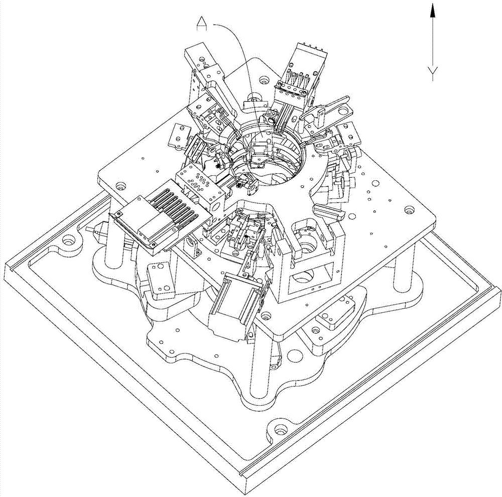
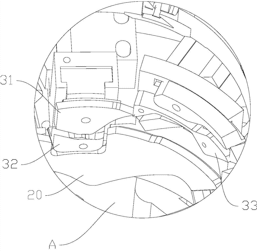
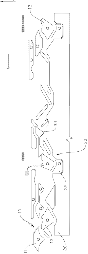
[0025] Hosiery machine triangle system, such as Figure 1-5 As shown, it includes the main road triangle system 10, the middle steel ring 20 and an additional auxiliary road triangle system 30. The main road triangle system 10 and the auxiliary road triangle system 30 are respectively located on both sides of the middle steel ring 20. Usually, the main road triangle system 10 is located on the opposite side of the auxiliary road cam system 30 in the circumferential direction of the middle steel ring 20; the main road cam system 10 includes the upper middle cam 11, the left yarn bending cam 12 and the right yarn bending cam 13; the auxiliary road cam system 30 includes Auxiliary road bending cam 31, auxiliary road insert 32 and flat needle plate 33, flat needle plate 33 is a strip plate arranged along the circumferential direction of middle steel ring 20, and the two ends of flat needle plate 33 are bent towards the auxiliary road Two protrusions are arranged in the direction o...


PUM


Abstract

The invention relates to the field of knitting hosiery machines and discloses a hosiery machine cam system. The hosiery machine cam system comprises a main circuit cam system, a middle steel ring and an auxiliary circuit cam system. The main circuit cam system and the auxiliary circuit cam system are located on the two sides of the middle steel ring respectively. The main circuit cam system comprises an upper middle cam, a left stitch cam and a right stitch cam. The auxiliary circuit cam system comprises an auxiliary circuit stitch cam, an auxiliary circuit insert and a plain stitch plate. The auxiliary circuit insert is located on the side, in the axial direction of the middle steel ring, of the auxiliary circuit stitch cam, and the plain stitch plate is located on the side, in the peripheral direction of the middle steel ring, of the auxiliary circuit stitch cam. The invention further discloses the stitch cams of the cam system. The hosiery machine cam system and the stitch cams have the advantages that other circuit of stitch cam system is placed on one side of the main circuit cam system of an existing single-needle-cylinder circular knit hosiery machine, the knitting efficiency is improved, and high application value is achieved.

Description

technical field [0001] The invention relates to the field of hosiery knitting machines, in particular to a hosiery machine cam system and a yarn bending cam applied to the cam system. Background technique [0002] A round hosiery machine refers to a hosiery machine that uses one needle cylinder to knit long, medium, and short socks and pantyhose. It can produce socks of various weaves such as plain stitch, plating, tuck, jacquard, terry and horizontal stripes. The main knitting parts are latch needles, sinkers, foot pieces and jacquard pieces. The butts of latch needles can be divided into long, medium and short. Generally, long heels and short heels are respectively arranged on half the circumference of the needle cylinder. The latch needle moves up and down in the groove of the needle cylinder for knitting. The sinker is located between the latch needles and moves radially in and out. Its function is to hold the loop when unwinding and pull the loop after looping. When...

Claims


Application Information

Patent Timeline
IPC IPC(8): D04B15/32
Inventor 丁孝君顾晓东陈超宗叶
Owner ZHEJIANG YEXIAO KNITTING MACHINERY
Why Eureka
Try Eureka