All-wet-joint precast prestressed underground continuous wall and construction method thereof

A technology for underground diaphragm walls and wet joints, which is applied in excavation, sheet pile walls, foundation structure engineering, etc. It can solve problems such as easy seepage, increase construction costs, and leaking reinforcement in walls, so as to delay cracking time and increase bending resistance Effect of stiffness, enhanced shear performance

Active Publication Date: 2014-06-04
SOUTHEAST UNIV
View PDF7 Cites 18 Cited by
  • Summary
  • Abstract
  • Description
  • Claims
  • Application Information

AI Technical Summary

Problems solved by technology

The shortcomings of this technology are: (1) The construction quality of the underground diaphragm wall is greatly affected by the stratum. In complex strata, there are usually quality problems such as wall shrinkage, collapse, wall leakage, insufficient wall thickness, and "bulging" ; (2) The construction quality at the joint affects the overall quality of the underground diaphragm wall
It is difficult to control the quality of the underwater operation of the locking pipe joint, which may easily cause the locking pipe to tilt, resulting in the vertical joints of the underground diaphragm wall not being straight, and prone to seepage and other phenomena
(3) The underground diaphragm wall with silt has quality problems such as falling water and large lateral deformation during foundation pit excavation
However, these walls are prone to groundwater leakage at the wall joints. In order to avoid leakage problems, the construction cost will often be increased.

Method used


Image

  • All-wet-joint precast prestressed underground continuous wall and construction method thereof
  • All-wet-joint precast prestressed underground continuous wall and construction method thereof
  • All-wet-joint precast prestressed underground continuous wall and construction method thereof

Examples


Embodiment Construction

[0034] The present invention will be further described below in conjunction with accompanying drawing.

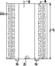
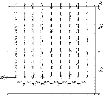
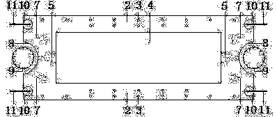
[0035] like figure 1 , figure 2 , image 3 and Figure 4 As shown, the prefabricated prestressed underground diaphragm wall with full wet joints of the present invention includes several wall sections 1 sequentially connected from top to bottom, and the wall sections 1 include a prefabricated box-shaped concrete structure 2, and a Prestressed tendon holes 3, the wall sections 1 are connected by a plug-in structure, the middle part of the section of the wall section 1 is a cavity 4, and the center of the wall section 1 along the length direction is provided with a concave groove section 8, so The upper and lower connection parts of the box-shaped concrete structure 2 are provided with a semi-conical hole 5, the semi-conical hole 5 communicates with the cavity 4 and the groove section 8, and concrete is poured in the semi-conical hole 5 to form a waterproof Wet joints, t...


PUM


Abstract

The invention provides an all-wet-joint precast prestressed underground continuous wall and a construction method of the all-wet-joint precast prestressed underground continuous wall. The continuous wall is formed by sequentially connecting a plurality of wall segments (1). The middle of the section of each wall segment (1) is provided with a cavity (4). Concave groove segments (8) are arranged at the center of the wall segments (1) in the length direction. Semi-conical holes (5) are formed in the upper connection parts and the lower connection parts of the wall segments (1). The semi-conical holes (5) are communicated with the cavities (4) and the concave groove segments (8). Water-proof wet joints are formed by pouring concrete in the semi-conical holes (5). According to the continuous wall, all the wall segments are connected through the wet joints, so that the problem of leakage at the connection parts of the wall segments is solved. By exerting prestressing force between the wall segments, the flexural rigidity, the anti-cracking ability and the lasting quality of the underground continuous wall are improved. Due to the fact that the underground continuous wall is connected with reinforcing mesh pieces, the shear-resistant performance between the wall segments is strengthened. As the wall segments are constructed on the ground, the quality of the continuous wall is easy to guarantee.

Description

technical field [0001] The invention relates to the field of design and construction of an underground diaphragm wall for building foundation pit engineering, in particular to a prefabricated prestressed underground diaphragm wall with full wet joints and a construction method for the underground diaphragm wall. Background technique [0002] The underground diaphragm wall construction technology originated in Europe. In 1938, Italy developed a construction method for constructing an underground diaphragm wall in a mud support deep groove. In 1950, it was the first to use deep mud tanks to build underground diaphragm walls in Italy. In the 1950s and 1960s, this technology was promoted in western developed countries, the former Soviet Union and Japan. In 1958, my country used this technology to build a dam cut-off wall. In the mid-1970s, this technology was applied to construction, coal mines and municipal industries. Due to its high rigidity, the underground diaphragm wall ...

Claims


Application Information

Patent Timeline
Patent Type & Authority Applications(China)
IPC IPC(8): E02D5/20E02D17/04
Inventor 金晓飞梁书亭朱筱俊张玉良
Owner SOUTHEAST UNIV
Why Eureka
Try Eureka