Square steel pipe column-h-shaped steel beam splicing outer sleeve connection method

A connection method, the technology of H-shaped steel, which is applied in the direction of construction and building construction, can solve the problems of difficult built-in positioning, difficult operation process, and many welded parts, and achieves the effects of convenient construction, shortened construction period, and simple structure

A connection method, the technology of H-shaped steel, which is applied in the direction of construction and building construction, can solve the problems of difficult built-in positioning, difficult operation process, and many welded parts, and achieves the effects of convenient construction, shortened construction period, and simple structure

CN103835374BActive Publication Date: 2019-05-03夏军武

Image

  • Square steel pipe column-h-shaped steel beam splicing outer sleeve connection method
  • Square steel pipe column-h-shaped steel beam splicing outer sleeve connection method
  • Square steel pipe column-h-shaped steel beam splicing outer sleeve connection method

Examples


Embodiment

[0021] The present invention will be described in detail below with reference to the drawings and specific embodiments.

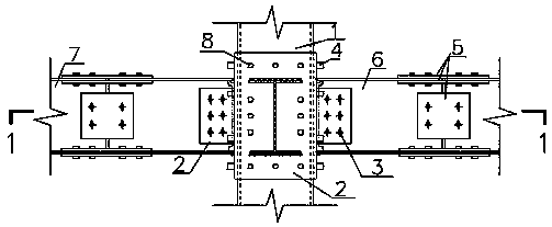
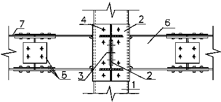
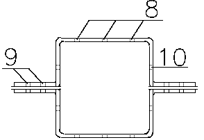
[0022] Such as Figure 1 to Figure 5 As shown, the present invention is a square steel pipe column-H-shaped steel beam splicing outer sleeve type connection method, which is mainly composed of square steel pipe column 1, U-shaped splicing outer plate 2, high-strength bolts 3, high-strength core bolts 4, splicing cover Plate 5, cantilever H-shaped steel short beam 6, H-shaped steel beam 7, plug welding hole 8, eversion lug plate 9 and core bolt hole 10. The square steel pipe column 1 has several groups, one of which is opposite to the pipe wall Corresponding core bolt holes 10 are provided on the U-shaped splicing outer shell plate 2 and corresponding core bolt holes 10 and plug welding holes 8 are also provided on the U-shaped splicing outer shell plate 2. The U-shaped splicing outer shell plate 2 is connected with the core through the high-strength core bolt ...


PUM


Abstract

The invention discloses a novel square steel tube column-H-shaped steel beam splicing outer sleeve type connecting method. A square steel tube column, a U-shaped splicing outer covering plate, high-strength bolts, high-strength core penetrating bolts, splicing cover plates, cantilever H-shaped steel short beams, H-shaped steel beams, plug welding holes, outwards-turning lug plates and core penetrating bolt holes are mainly related. The structure is simple, the construction is convenient, the good anti-seismic property is achieved, the procedures at the site construction stage are simplified and are carried out easily, the construction production efficiency is effectively improved, the construction time is shortened, and the construction cost is saved.

Description

Technical field [0001] The invention relates to the technical field of construction, a method for connecting square steel tube columns and H-shaped steel beams in a multi-high-rise steel frame structure, and is an improved form of outer steel plate type joints, specifically a square steel tube column-H-shaped steel Beam splicing outer sleeve type connection method. Background technique [0002] The joint connection of square steel tube column-H-beam in my country mostly adopts partitions to strengthen the stiffness of the joints. The main forms are internal partitions, through partitions and external partitions. Inner diaphragm joints are only suitable when the size of the pipe string is large, because when the side length of the pipe string is small, it is not only difficult to weld, but also hinders the pouring of concrete in the pipe. In addition, the beam flange and the inner diaphragm are at the same place on the column wall. Penetration welds need to be applied on both sid...

Claims


Application Information

Patent Timeline
03 May 2019
Publication
CN103835374B
IPC
E04B1/58
Inventors
夏军武; 张志雄