Circular section synchronous rotary jet grouting device

A grouting device and section technology, which is applied to shaft equipment, shaft lining, mining equipment, etc., can solve the problems of unfavorable grouting to control the formation of mud jacket, slow grouting effect and small grouting amount, etc. Body deformation, reduce friction, control the effect of land subsidence

Inactive Publication Date: 2014-06-04
上海盾构设计试验研究中心有限公司 +2
View PDF5 Cites 12 Cited by
  • Summary
  • Abstract
  • Description
  • Claims
  • Application Information

AI Technical Summary

Problems solved by technology

[0004] The technical solution of this patent sets a plurality of fixed grouting holes on the outer circumference of the steel pipe joint. Due to the fixed positions of the grouting holes, the amount of grouting near the grouting holes is large, and the amount of grouting away from the grouting holes is large. Small, thus detrimental to grout control and mud jacket formation, and slower to achieve desired grouting results

Method used


Image

  • Circular section synchronous rotary jet grouting device
  • Circular section synchronous rotary jet grouting device
  • Circular section synchronous rotary jet grouting device

Examples


Embodiment Construction

[0024] The present invention will be further described below in conjunction with the accompanying drawings and specific embodiments, but the protection scope of the present invention should not be limited thereby.

[0025] The circular cross-section synchronous rotary jet grouting device of the present invention is installed between the tool pipes at the tail of the pipe jacking machine, and advances together with the pipe jacking machine, and can inject grout around the pipe jacking machine in time to quickly and evenly form the mud sleeve, effectively Reduce the friction between the tunnel segment and the soil, and fill the shield tail gap.

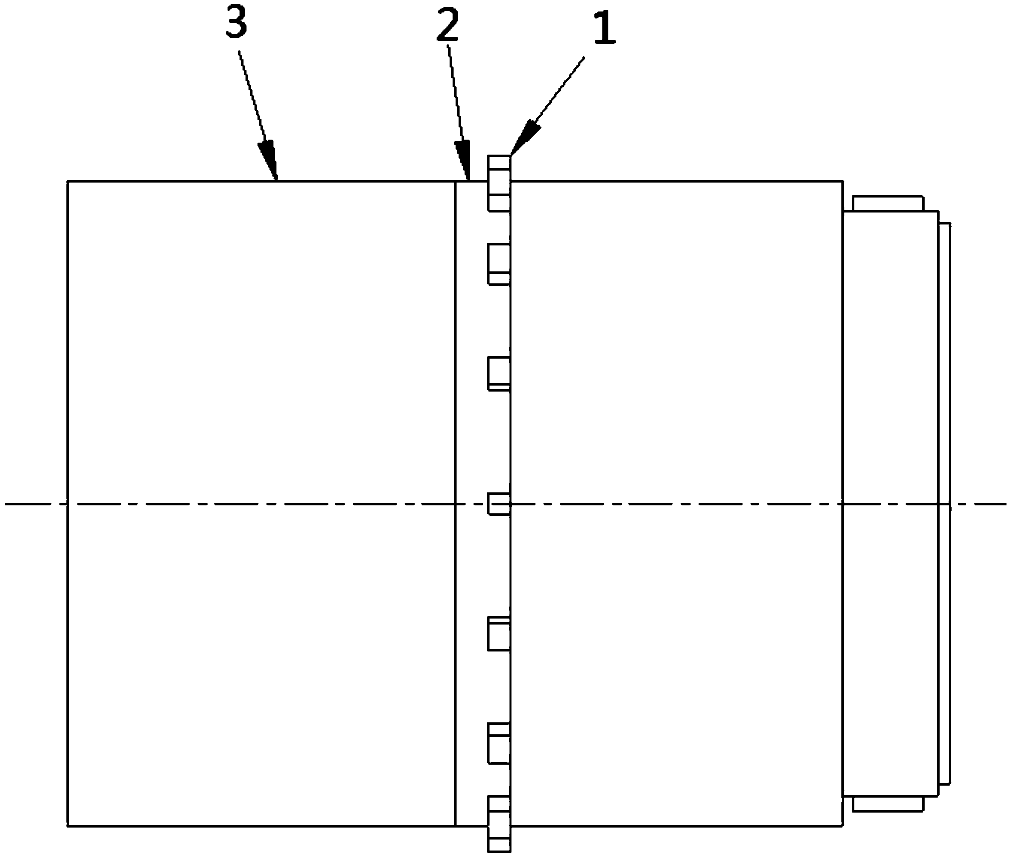
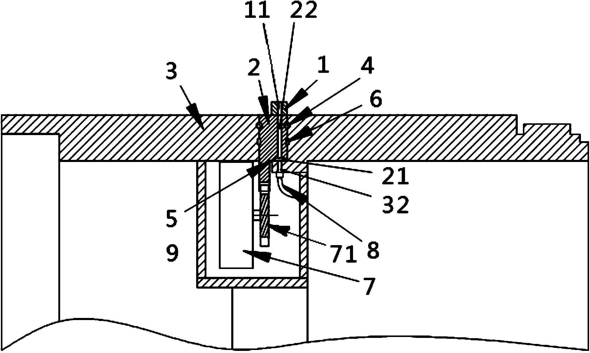
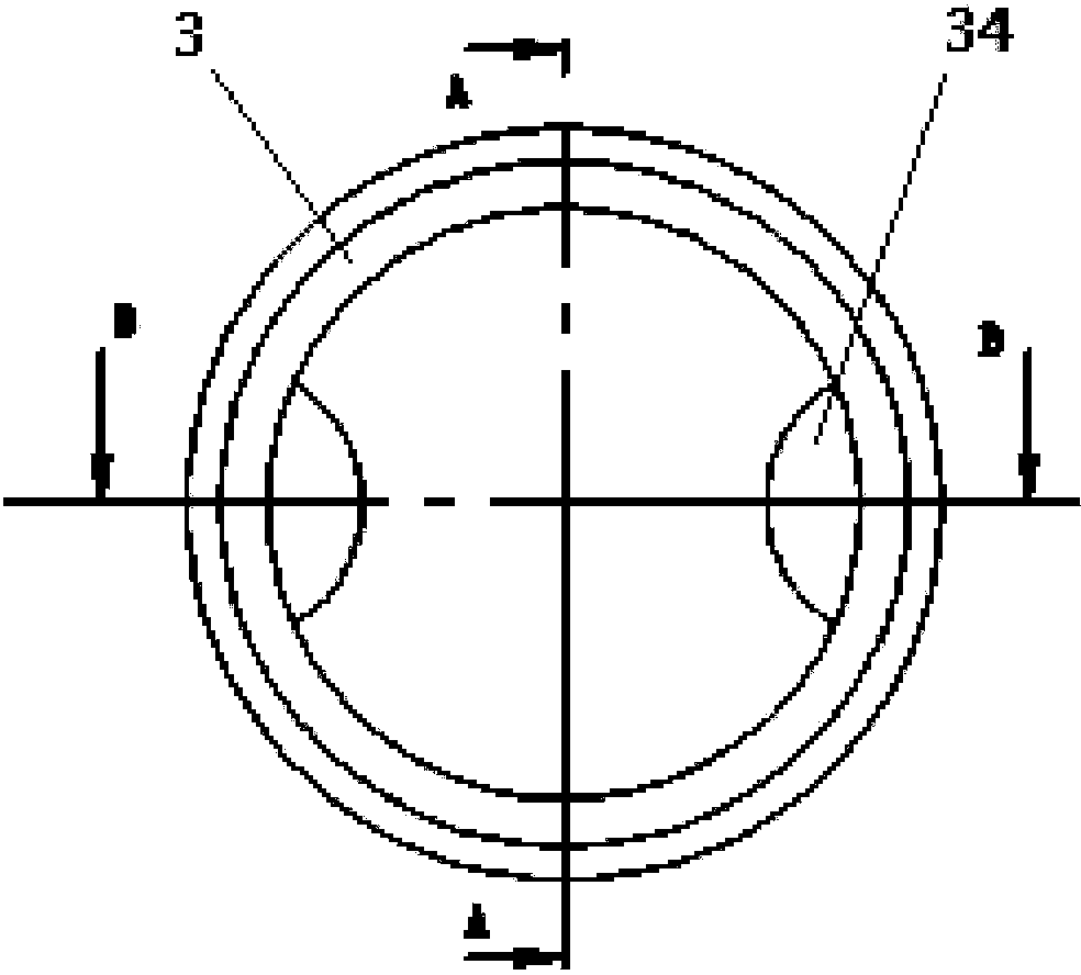
[0026] see figure 1 and figure 2 , the diagram shows a circular cross-section synchronous rotary jet grouting device including a steel pipe section 3, a grouting pipe 8, a swivel 2, a motor 7 and a number of nozzles 1.

[0027] Please refer to figure 2 , image 3 , Figure 4 and Figure 5 , the two ends of the steel pipe section...


PUM


Abstract

A circular section synchronous rotary spray grouting device comprises a steel pipe section, a grouting pipe and a plurality of sprayers. Two ends of the steel pipe section are connected with tool pipes. The grouting pipe is used for conveying grout. The sprayers are driven to rotate by a plurality of motors and used for grouting between the steel pipe section of a soil body. A peripheral annular groove and a conveying hole communicating with the grouting pipe are formed in the wall of the steel pipe section. A rotary ring is embedded in to the annular groove through slide support blocks on two sides and can rotate. A peripheral grout storage groove communicated with the conveying hole of the steel pipe section and a plurality of grout conveying holes communicated with the peripheral grout storage groove and axially penetrating the rotary ring are formed in the inner wall of the rotary ring. The sprayers are fixedly connected to the outer wall of the rotary ring and rotates along with the rotary ring. Each sprayer is provided with a grouting hole communicated with the corresponding grout conveying holes. The circular section synchronous rotary spray grouting device has the advantages that timely grouting of the periphery of a pipe push bench can be achieved, even grout sleeves can be formed fast, friction between tunnel tube pieces and the soil body is lowered, soil body deformation is prevented, ground subsidence is controlled, and post tunnel deformation is reduced.

Description

technical field [0001] The invention relates to tunnel construction equipment, in particular to a synchronous rotary jet grouting device suitable for circular sections, belonging to the field of construction machinery. Background technique [0002] The construction process of the tunnel pipe jacking method is to push the tool pipe and roadheader into the soil layer from the working pit with the help of the main jacking cylinder, the thrust between the pipes and the relay room. A section of pipe continues to be jacked until the tunnel is penetrated and the pipe jacking machine reaches the receiving pit. The key issue in pipe jacking construction is the length of one-time jacking. To achieve an ideal length of one-time jacking, the key lies in the jacking force. The most important factor affecting the jacking force is the friction between the pipe and the soil. The current effective drag reduction measures are generally to inject mud between the pipe and the soil. One is to f...

Claims


Application Information

Patent Timeline
Patent Type & Authority Applications(China)
IPC IPC(8): E21D11/10
Inventor 庄欠伟陈实徐天明杨正彭世宝何晓朱敏明陆晓华
Owner 上海盾构设计试验研究中心有限公司
Why Eureka
Try Eureka