
Data center server cooling equipment cabinet

A technology for server cabinets and cooling cabinets, which is applied to data processing power supplies, electrical digital data processing, and digital data processing components, etc. It can solve problems such as failure to meet server heat dissipation requirements, server overheating, and low heat dissipation efficiency. Stable operation, reduced operating cost, and short construction period

Active Publication Date: 2014-06-04
BEIJING FULLLINK OREITH TECH CO LTD
View PDF7 Cites 8 Cited by
  • Summary
  • Abstract
  • Description
  • Claims
  • Application Information

AI Technical Summary

Problems solved by technology

[0003] The heat dissipation of the server is always the focus of the industry. Today, with the increasing computing density and increasing power consumption, the heat dissipation problem of servers, especially data centers with a large number of application servers, will always be "lingering". Now, Because external heat dissipation is difficult to completely solve the problem, and the heat dissipation efficiency is low, it often causes local overheating inside the server, so that the heat dissipation requirements of the server cannot be met, so more and more server manufacturers have focused on the heat dissipation of the server inside the server
For server heat dissipation, especially internal heat dissipation, simply increasing the number of fans or increasing the fan speed cannot solve the problem well. The more fans, the faster the speed, the more power consumption, and the greater the noise. For users, power consumption and noise are also big problems

Method used


Image

  • Data center server cooling equipment cabinet
  • Data center server cooling equipment cabinet
  • Data center server cooling equipment cabinet

Examples


Embodiment Construction

[0029] Specific embodiments of the present invention are described with reference to the above drawings.

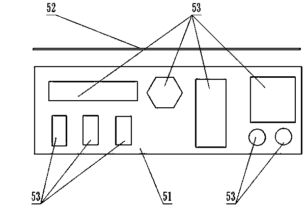
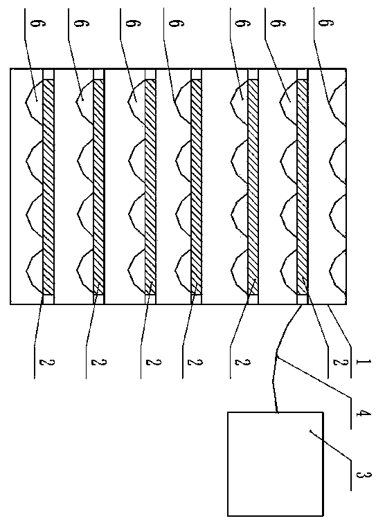
[0030] like figure 1 The sectional view of the server casing of the present invention includes a server casing (5) and a server (7), and the server casing (5) includes a server casing base (51) and a server casing upper cover (52). The bottom plate of the chassis base (51) and the four side plates of the bottom plate are cast integral structures; the chassis base (51) is a metal shell with good thermal conductivity, and the chassis base (51) is a metal shell with good thermal conductivity. The inside of the bottom plate of (51) is cast with a groove or convex structure according to the structural shape of the electronic component (71) with a large heat generation on the server (7), so that the bottom plate of the casing base (51) is in contact with the server (7). (7) The electronic components (71) with high heat generation can be in close contact; there is a space betwe...


PUM


Abstract

The invention discloses a data center server cooling equipment cabinet which comprises a server equipment cabinet, a phase change heat transmission system, server machine shells and spring pieces for fixing the server machine shells. The phase change heat transmission system comprises a plurality of heat exchangers arranged in the server equipment cabinet, an outdoor cooling device and connecting pipelines. The heat exchangers are arranged on support layers for placing of servers in the server equipment cabinet respectively. The server machine shells are placed on the upper portions of the heat exchangers, the servers are sealed in the server machine shells, air cooling does not exist in the whole data center server cooling equipment cabinet, server heating units are in direct contact with the server machine shells, the server machine shells are in direct contact with the heat exchangers placed in the server machine cabinet, contact heat transmission is achieved, and heat transmission efficiency is improved. According to the data center server cooling equipment cabinet, server placing density can be increased, building cost is low, a building cycle is short, and the running cost of a whole data center is greatly lowered.

Description

technical field [0001] The invention relates to a server cabinet, in particular to a data center server cooling cabinet capable of realizing contact heat transfer. Background technique [0002] With the improvement of server integration, the power of a single rack in the data center computer room has been greatly increased. The rapid development of data centers and their high energy consumption characteristics have been highly concerned by the society. It is of great significance to carry out energy-saving transformation or build high-energy-efficiency data centers for energy-saving and consumption-reducing work. According to statistics, the power of the latest blade server rack is as high as 15kW, the power of the desktop server rack is 1.5kW, and the power of the modular server rack is 5kW. High power consumption will inevitably generate high heat generation, which makes the local heating become very severe, the temperature gradient changes greatly, and the ventilation an...

Claims


Application Information

Patent Timeline
Patent Type & Authority Applications(China)
IPC IPC(8): G06F1/20G06F1/32
CPCG06F1/20
Inventor 祝长宇丁式平何慧丽
Owner BEIJING FULLLINK OREITH TECH CO LTD
Learn More