This helps you quickly interpret patents by identifying the three key elements:
Problems solved by technology
Method used
Benefits of technology
Problems solved by technology
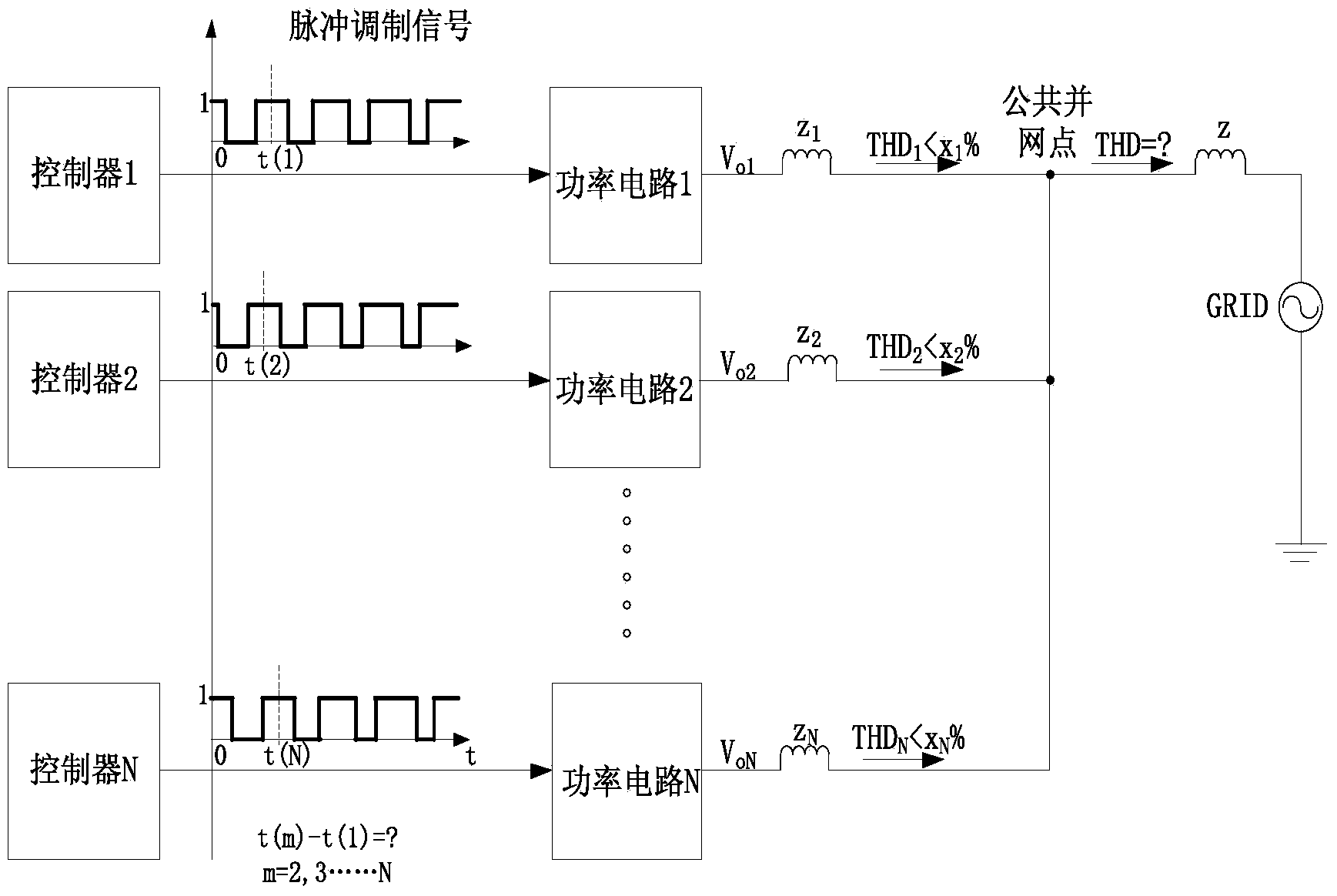
The total harmonic distortion of each inverter output current is less than a certain value, namely THD m m %(m=1,2...N), each inverter is independently controlled by the controller, and the pulse width modulation waves of each inverter do not meet the phase relationship that can make the harmonic current cancel each other between the inverters, which is figure 2 Among them, t(m)-t(1)=? is an uncertain value, and the disorderly superimposed current harmonics can make the total harmonic distortion rate of the grid current exceed the grid requirements, that is, figure 2 Medium THD
Existing patents can only reduce the output current harmonics of one inverter but cannot control the problem of current harmonics injected into the grid by the public grid-connected point. Some articles mention the synchronization of different inverters, but they are all aimed at running inverters in parallel at the same location Synchronization of power frequency between inverters, without mentioning the problem of harmonic elimination, this patent proposes a global synchronous pulse width modulation method, which can effectively reduce the common Current harmonics injected into the grid at the grid-connected point
Method used
Image
Click on the blue label to locate the original text in one second.
Reading with bidirectional positioning of images and text.
Examples
Embodiment 1
[0109] Corresponding to the situation where the inverters are not grouped, there are 4 inverters in the system connected to the common grid-connected point, the switching frequency is 20k, the DC side voltage is Vdc, and the inductance between the common grid-connected point is L, wrong Inverters are grouped, N=4, m=1,2,3,4.
[0117] Step 12, locate the synchronization time interval for 1 minute, ...
Embodiment 2
[0122] Corresponding to the situation where the inverters are not grouped, there are 5 inverters in the system connected to the common grid-connected point, the switching frequency is 20k, the DC side voltage is Vdc, and the inductance between the common grid-connected point is L, wrong Inverters are grouped, N=5, m=1,2,3,4,5.
[0123] In step 21, the synchronization unit obtains the switching frequency of each inverter, the DC side voltage, and the reactance to the common grid connection point.
[0137] Step 31: In the case of grouping inverters, there are 11 inverters in the system connected to the common grid connection point, and the switching frequency is 40k, but when the DC side voltage and the reactance to the public grid connection point are different, group them The label, the DC side voltage parameters and reactance parameters of each inverter are shown in Table 1. Here, an example is used for analysis, which does not represent the actual parameter value. Here, according to one method, the V in each group dcm / L m They are divided into 4 groups by the method of sum and similarity, and the groups are shown in Table 1. Inverters 1, 2, and 3 are the first group, inverters 4, 5, and 6 are the second group, and inverters 7, 8, 9 is the third group, inverters 10 and 11 are the fourth group, N=4, m=1, 2, 3, 4.
[0138] Table 1
[0139]
[0140] T c = 1 40 × ...
PUM
Abstract
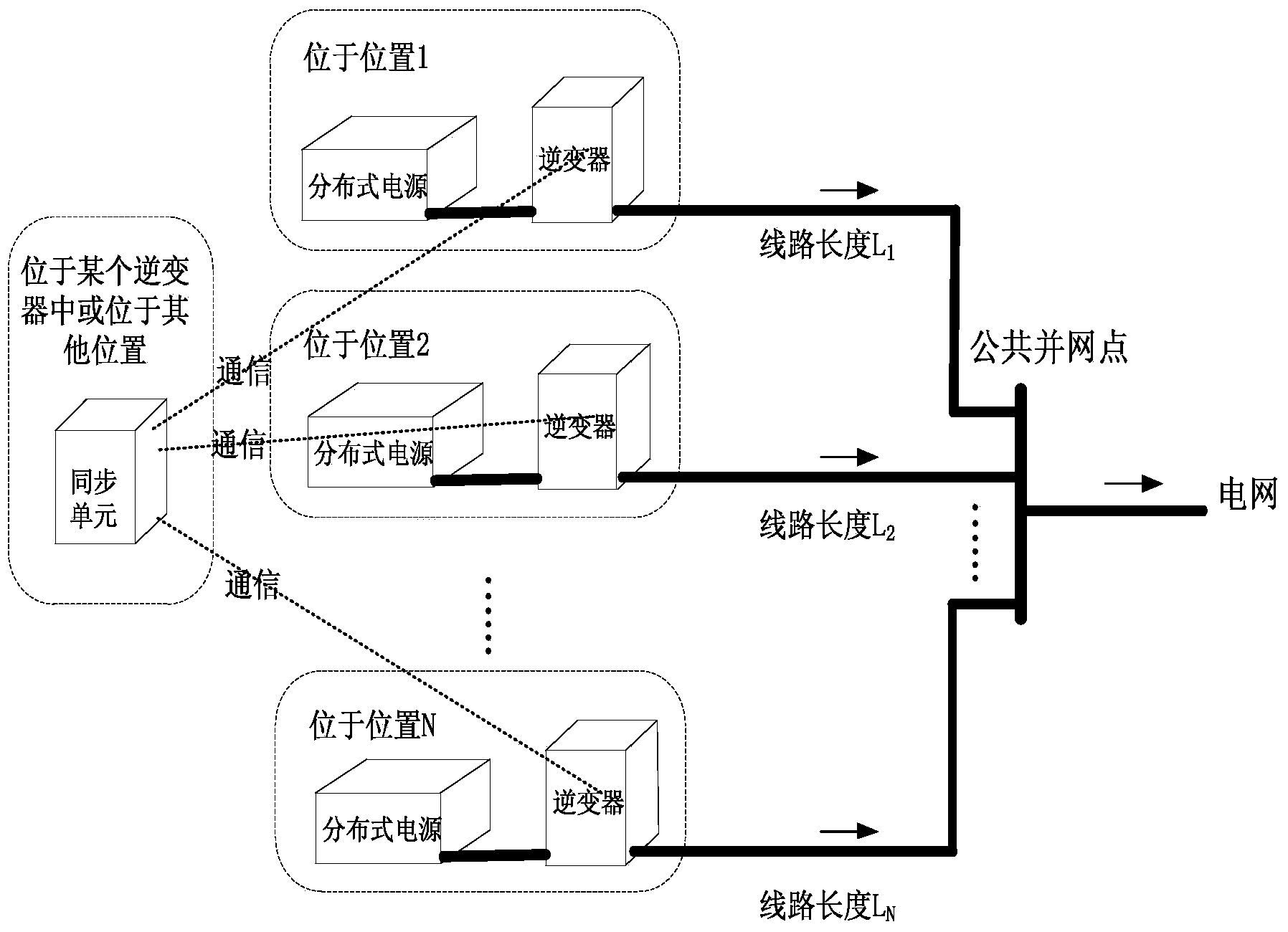
The invention discloses a global synchronization pulse width modulationsystem and method of a distributed grid-connected invertersystem. The system comprises a main control unit and a plurality of grid-connected inverters located at different geographic positions. The grid-connected inverters are connected with distributed power supplies respectively and are all connected with a power grid through a public grid connection point. Communication between the main control unit and all the grid-connected inverters is carried out through communication channels. The main control unit receives information of each grid-connected inverter. After a global synchronization strategy is determined, global synchronization signals of the global synchronization strategy are sent to the grid-connected inverters respectively, the grid-connected inverters adjust the phases of pulse width modulationwaves of the grid-connected inverters according to the global synchronization signals so that the pulse width modulationwaves of the grid-connected inverters can have a phase difference meeting the requirement for harmonic offset, and accordingly harmonic currents injected into the power grid by the grid-connected inverters can be offset. The global synchronization pulse width modulation system and method of the distributed grid-connected inverter system have the advantages that the problem of disordered superposition of the harmonic currents of the inverters can be solved and the harmonic currents can be offset by each other among the distributed inverters.
Description
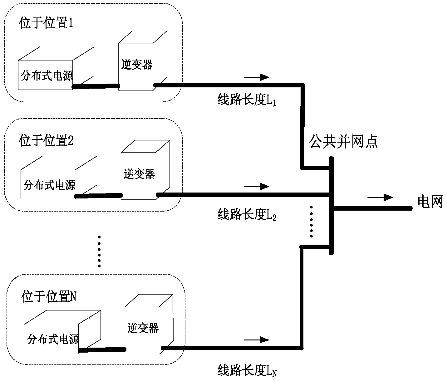
technical field [0001] The invention relates to a global synchronous pulse width modulation system and method of a distributed grid-connected inverter system. Background technique [0002] The function of the distributed grid-connected inverter system is to connect distributed power sources to the grid through the grid-connected inverter. In order to reduce the impact of grid-connected inverter output harmonics on the grid, many methods have been proposed in existing patents, but the research objects of these methods are all single inverters, which can only reduce the harmonics of one inverter. [0003] Usually, grid-connected inverters are distributed in different locations, such as figure 1 As shown, each grid-connected inverter is independently controlled by its own controller to send or absorb power to the grid. The output waveform quality of the inverter can be controlled by means of pulse width modulation. Although each inverter controls the total harmonic distortio...
Claims
Application Information
Patent Timeline
Application Date:The date an application was filed.
Publication Date:The date a patent or application was officially published.
First Publication Date:The earliest publication date of a patent with the same application number.
Issue Date:Publication date of the patent grant document.
PCT Entry Date:The Entry date of PCT National Phase.
Estimated Expiry Date:The statutory expiry date of a patent right according to the Patent Law, and it is the longest term of protection that the patent right can achieve without the termination of the patent right due to other reasons(Term extension factor has been taken into account ).
Invalid Date:Actual expiry date is based on effective date or publication date of legal transaction data of invalid patent.

