
Multifunctional charging station

A charging station and multi-functional technology, applied in the field of charging stations, can solve the problems of poor charging, only one voltage, high maintenance cost, etc., and achieve the effects of various types, reducing the pressure on the power grid, and reducing maintenance costs

Inactive Publication Date: 2014-06-04
姬脉良
View PDF0 Cites 6 Cited by
  • Summary
  • Abstract
  • Description
  • Claims
  • Application Information

AI Technical Summary

Problems solved by technology

[0002] The existing charging station mainly charges the energy storage box in the charging station through a dedicated power supply network, and then outputs the electric energy in the energy storage box. When there is a problem with the power supply of the grid, the charging station will not work
Therefore, there is a hybrid charging station of wind and electricity in the market, which uses wind energy, solar energy and power grid to replace the traditional grid power supply, but this charging station is still a part of the power grid and is not separated from the grid. When there is a problem with the power grid for a long time, it will not be possible to provide emergency power, and this charging station is expensive, high in maintenance costs, and requires specialized personnel to take care of it. There is a single payment method to choose, and only one voltage output. The situation that the money cannot be recharged, and the electricity cannot be recharged

Method used


Image

  • Multifunctional charging station
  • Multifunctional charging station
  • Multifunctional charging station

Examples


Embodiment Construction

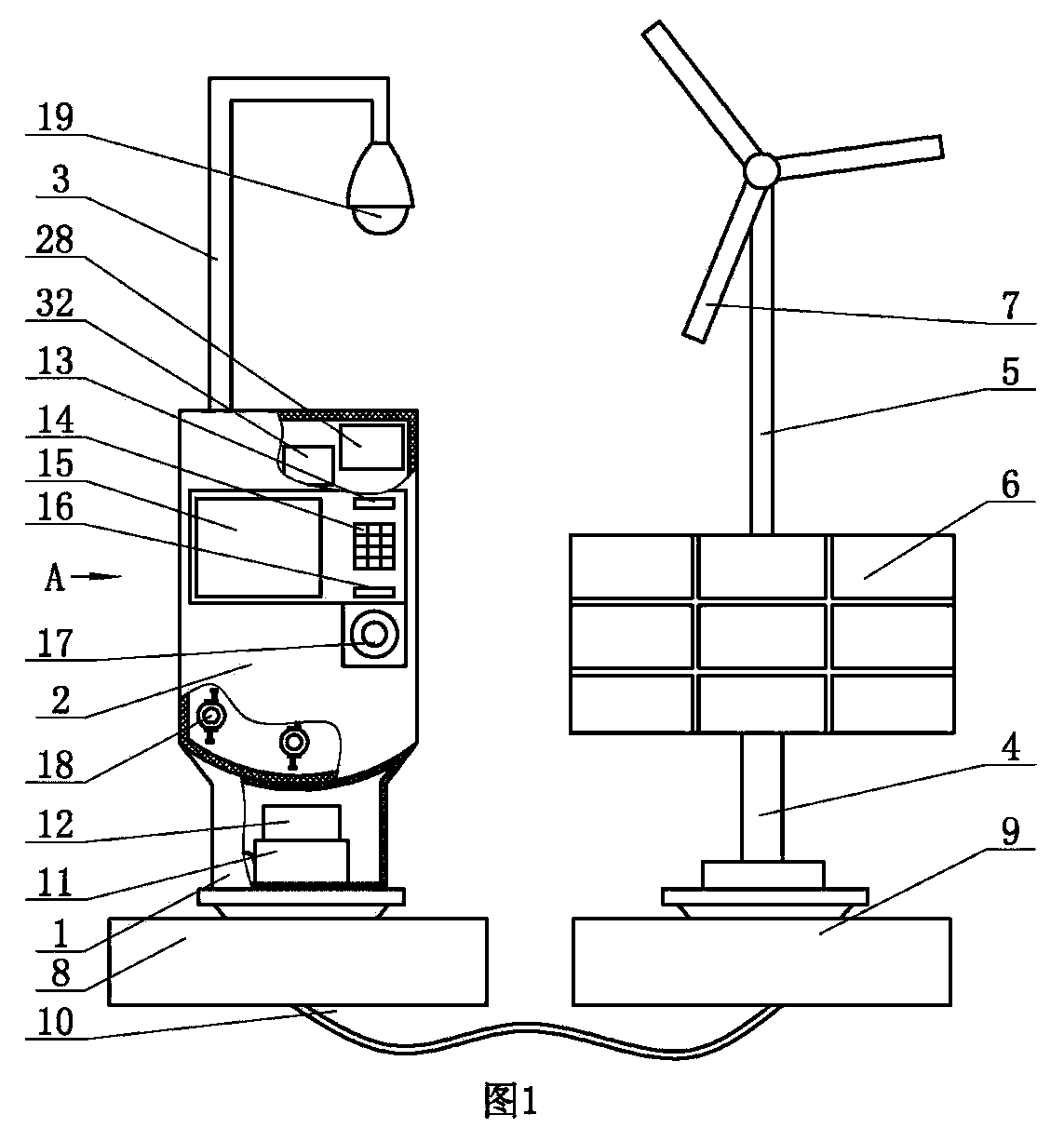
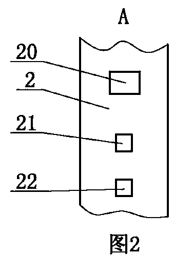
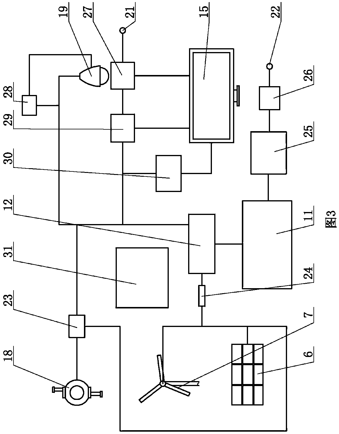
[0009] The present invention includes a support seat 1 and a support column 4, such as figure 1 As shown, a storage battery 11 and a wind-solar hybrid controller 12 are installed in the support base 1, a housing 2 is installed above the support base 1, a main board 32 is installed in the housing 2, a power port and a payment port are respectively arranged on the housing 2, and the power port and the battery 11 is connected, the payment port is connected with the main board 32, and the main board controls the payment port to realize automatic charging; a support rod 5 is installed above the support column 4, a solar panel 6 is installed on the support rod 5, and a fan 7, a solar panel 6 and a fan 7 are installed on the top of the support rod 5 Connected to the storage battery 11 through the wire 10, this structure can use wind energy and solar energy to provide electricity for people, without using the power grid, reduce the pollution caused by oil and coal power generation, and...


PUM


Abstract

The invention provides a multifunctional charging station. The charging station comprises a support base and a support column. A storage battery and a wind-solar complementation controller are disposed in the support base. A housing is mounted on the support base. A mainboard is installed in the housing. A power supply port and a payment port are arranged in the housing separately. The power supply port is connected to the storage battery, and the payment port is connected to the mainboard. A support rod is mounted on the support column, and a solar panel is installed on the support rod. A fan is installed on the top end of the support rod. The solar panel and the fan are connected to the storage battery by wires. The beneficial effects are that the charging station is not connected to a power grid, and thus reduces pressure on the power grid; the charging station fully utilizes solar energy and wind energy to achieve green generating, and thus can supply people with emergency power for a long period of time when a power grid fault happens; the charging station is equipped with a camera to prevent manual damage and to monitor usage situations of the charging station; many payment methods, such as bank cards, membership cards, coins and so on, are available for selection; there are many voltage output choices; and it is not necessary to specially assign a person to look after the charging station, and thus the maintenance cost is reduced.

Description

technical field [0001] The invention relates to a charging station, in particular to a multifunctional charging station. Background technique [0002] The existing charging station mainly charges the energy storage box in the charging station through a dedicated power supply network, and then outputs the electric energy in the energy storage box. When there is a problem with the power supply of the grid, the charging station will not work. Therefore, there is a hybrid charging station of wind and electricity in the market, which uses wind energy, solar energy and power grid to replace the traditional grid power supply, but this charging station is still a part of the power grid and is not separated from the grid. When there is a problem with the power grid for a long time, it will not be possible to provide emergency power, and this charging station is expensive, high in maintenance costs, and requires specialized personnel to take care of it. There is a single payment meth...

Claims


Application Information

Patent Timeline
Patent Type & Authority Applications(China)
IPC IPC(8): H02J7/00H02J9/00
Inventor 姬脉良
Owner 姬脉良
Learn More