Buck power converter

A power converter and voltage technology, applied in the direction of output power conversion devices, instruments, electrical components, etc., can solve problems such as noise and ringing, and achieve the effect of reducing noise and ringing phenomenon.

Active Publication Date: 2014-06-04
EXCELLIANCE MOS
View PDF10 Cites 10 Cited by
  • Summary
  • Abstract
  • Description
  • Claims
  • Application Information

AI Technical Summary

Problems solved by technology

If the load RL is light load, the step-down power converter 100 will enter the discontinuous conduction mode (discontinuous-conduction mode, DCM), and after the current on the inductor L1 decreases to zero, the power transistor Q1 and the inductor L1 The voltage VB on the coupling terminal of the ringing phenomenon will occur, and then generate unnecessary noise

Method used


Image

  • Buck power converter
  • Buck power converter
  • Buck power converter

Examples


Embodiment Construction

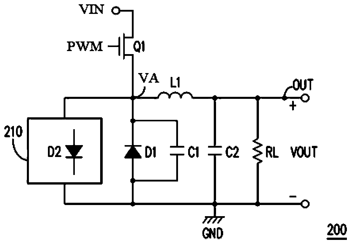
[0039] Please refer to the following figure 2 , figure 2 is a schematic diagram of a step-down power converter 200 according to an embodiment of the present invention. The buck power converter 200 includes a power transistor Q1 , an inductor L1 , a diode D1 and an anti-ringing circuit 210 . The power transistor Q1 has a first terminal (such as a source), a second terminal (such as a drain) and a control terminal (such as a gate), and its first terminal receives an input voltage VIN, and its control terminal receives a pulse width modulation signal PWM. The transistor Q1 is turned on or off according to the pulse width modulation signal PWM. The second terminal of the power transistor Q1 is coupled to the inductor L1, and the other terminal of the inductor L1 is coupled to the output terminal OUT of the step-down power converter 200 to generate the output voltage VOUT.

[0040] The diode D1 is connected in series between the second terminal of the power transistor Q1 and t...


PUM


Abstract

Disclosed is a buck power converter. The buck power converter comprises a power transistor, an inductor, a first diode and an anti-ringing circuit. The power transistor is provided with a first end, a second end and a control end. The first end receives an input voltage. The control end receives a pulse-width modulation signal. The anti-ringing circuit detects a detection voltage at the second end of the power transistor, and according to the detection voltage, provides at least one second diode for series connection between the second end of the power transistor and a reference grounding end in a forward bias mode so as to clamp the voltage value of the detection voltage.

Description

technical field [0001] The present invention relates to a step-down power converter, and more particularly to a step-down power converter capable of reducing ringing. Background technique [0002] figure 1 is a well-known circuit diagram of a step-down power converter 100, wherein the step-down power converter 100 includes a power transistor Q1, a diode D1, an inductor L1, and capacitors C1 and C2, and the step-down power converter 100 receives an input The voltage VIN is used to generate the output voltage VOUT to drive the load RL. [0003] Wherein, the power transistor Q1 is turned on or off according to the received pulse width modulation signal PWM, and the step-down power converter 100 converts the current from the received input voltage VIN through the process of the power transistor Q1 being turned on and off. The input terminal IN of the step-down power converter 100 is transmitted to the output terminal OUT of the step-down power converter 100 . When the power t...

Claims


Application Information

Patent Timeline
IPC IPC(8): H02M3/155
Inventor 林宝全林素圆周宏哲
Owner EXCELLIANCE MOS
Why Eureka
Try Eureka