
LED chip mounting feeding device

A technology of LED chip and feeding device

Inactive Publication Date: 2014-06-04
SHAANXI ZIZHU ELECTRON
View PDF0 Cites 2 Cited by
  • Summary
  • Abstract
  • Description
  • Claims
  • Application Information

AI Technical Summary

Problems solved by technology

[0003] The purpose of the present invention is to overcome the deficiencies in the above-mentioned prior art, to provide a feeding device for mounting LED chips, which has a simple structure, reasonable design and good use effect, and can effectively solve the problem of slow feeding speed of the existing feeder, if used at the same time Simultaneous feeding of multiple feeders will lead to a more complicated structure of the entire feeding device, and the operation is stable at the same time, which improves the quality of placement

Method used


Image

  • LED chip mounting feeding device
  • LED chip mounting feeding device

Examples


Embodiment Construction

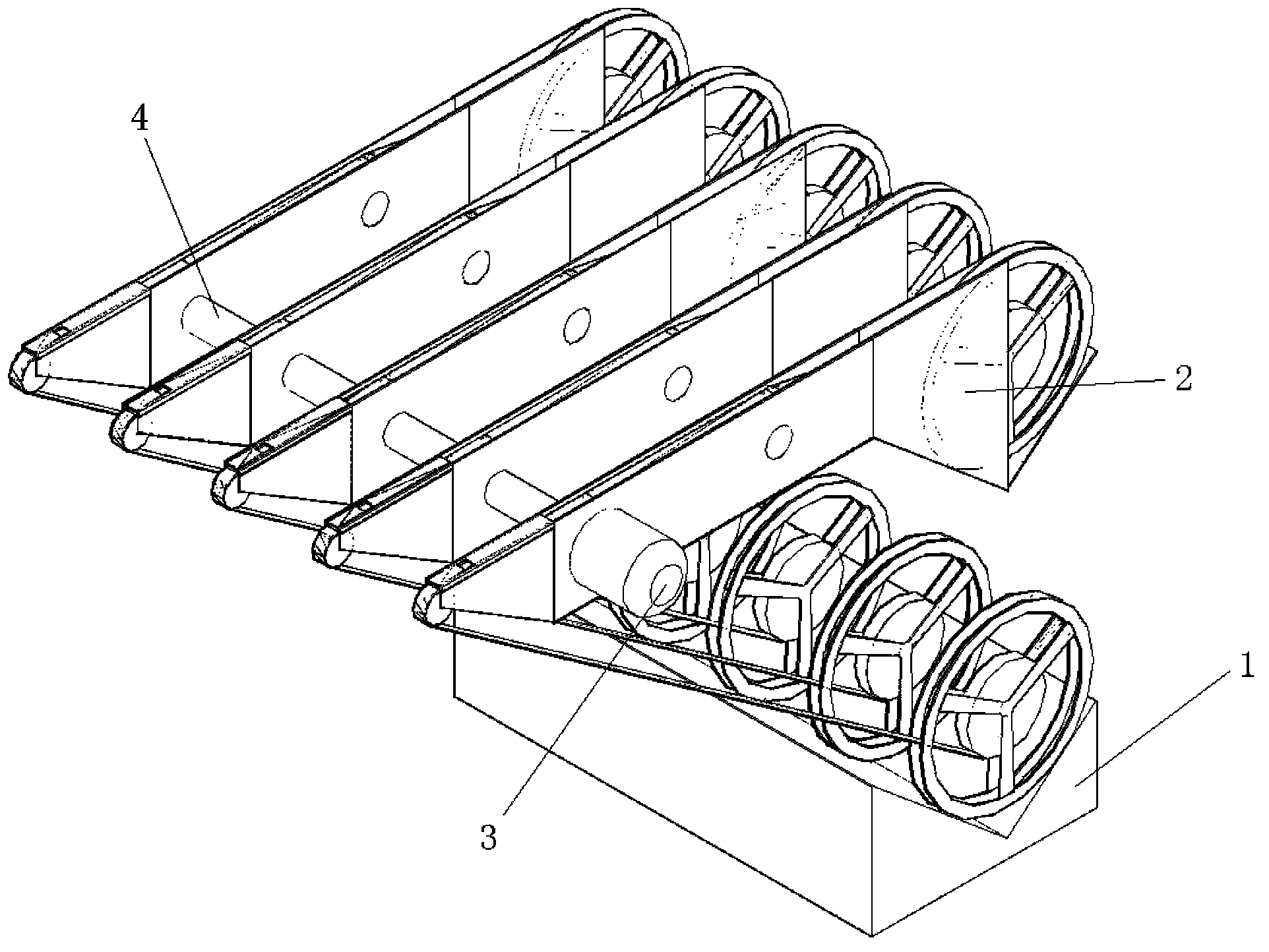
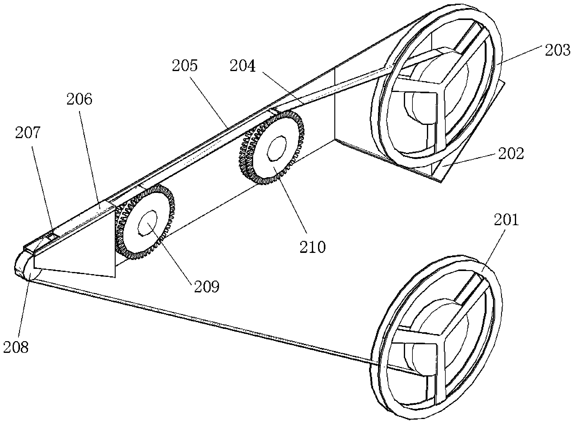
[0020] Such as figure 1 and figure 2 As shown, the present invention includes a feeding unit 2, a return rack 1, a connecting shaft 4 and a drive motor 3, the number of the feeding unit 2 is multiple and a plurality of feeding units 2 are connected by a connecting shaft 4, and the driving motor 3 is fixedly installed on one end of the connecting shaft 4 and is used to drive the connecting shaft 4 to rotate; the feeding unit 2 includes a storage part, a feeding part, a picking part and a feeding part, and the storage part includes a storage rack 202 and a setting The storage roller 203 in the storage rack 202, the bottom of the storage rack 202 is V-shaped, the LED feed belt 204 is wound on the storage roller 203, and the feeding part includes a material connected to the storage rack 202. The feeding frame 205 and the driving sprocket 209 and the feeding sprocket 210 installed on the side wall of the feeding frame 205, the feeding sprocket 210 is rotatably mounted on the cent...


PUM


Abstract

The invention discloses an LED chip mounting feeding device comprising feeding units, a feeding-back rack, a communication shaft and a drive motor. The feeding units are connected through the communication shaft. The drive motor is installed on one end of the communication shaft. Each feeding unit comprises a storage portion, a feeding portion, a pickup portion and a feeding-back portion. The storage portion comprises a storage rack and a storage roller arranged in the storage rack. An LED feeding belt is wound around the storage roller. The feeding portion comprises a feeding rack connected with the storage rack and a drive chain wheel and a feeding chain wheel which are installed on the sidewall of the feeding rack. The communication shaft passes through the feeding rack of each feeding unit. The pickup portion comprises a pickup rack connected with the feeding rack. The pickup rack is provided with a pickup opening. The feeding-back portion comprises a feeding-back wheel and a feeding-back roller. The LED feeding belt passes through the feeding chain wheel, the drive chain wheel and the feeding-back wheel successively and then is wound around the feeding-back roller. According to the invention, a plurality of LED feeding belts can be transferred at the same time, the transfer speed is fast, and the chip mounting quality can be ensured.

Description

technical field [0001] The invention relates to an LED placement machine system, in particular to a feeding device for mounting LED chips. Background technique [0002] Generally speaking, the LED placement machine is one of the SMT (Surface Mount System) placement machines. With the development of LED technology, the traditional SMT placement machine can no longer meet the production needs of the LED industry. At this time, the LED The placement machine came into being. LED placement machine is a SMT placement equipment specially designed and customized for the LED industry. It is used to realize the assembly of large quantities of LED circuit boards, and the equipment requires fast speed. The structure of the traditional LED chip mounting feeder is complicated, and the feeding speed is slow, and if multiple feeders are used to feed at the same time, the structure of the entire feeding device will be more complicated, which will easily make the operation unstable and affec...

Claims


Application Information

Patent Timeline
Patent Type & Authority Applications(China)
IPC IPC(8): H05K13/02H05K3/30
Inventor 田伟国
Owner SHAANXI ZIZHU ELECTRON
Learn More