Grid stirring flocculation reaction device

A technology of reaction equipment and grid flocculation, which is applied in the direction of flocculation/sedimentation water/sewage treatment, etc., can solve the problems of heavy maintenance workload of mechanical flocculation tanks, large dependence on external environmental factors, difficult process control, etc., so as not to block the mesh , The effect of shortening the flocculation time and improving the water flow conditions

Inactive Publication Date: 2014-06-11
JIANGSU JINGYUAN ENVIRONMENTAL PROTECTION
View PDF5 Cites 1 Cited by
  • Summary
  • Abstract
  • Description
  • Claims
  • Application Information

AI Technical Summary

Problems solved by technology

[0002] The flocculation reaction process in the traditional water treatment process is a unit purification process centered on the formation of flocs, and its effect is determined by the chemical action of the flocculant and the physical action of the flocculation reaction facility. There are two types of mechanical flocculation reaction facilities and hydraulic flocculation reaction facilities, and the grid flocculation tank and mechanical flocculation tank are the typical forms of these two reaction facilities. In the grid flocculation tank, raw water and chemicals are mixed and formed by hydraulic flocculation equipment. Large and dense solid flocs visible to the naked eye, the mechanical flocculation tank uses the motor to drive the agitator through the deceleration device to stir the water; but there are many shortcomings due to a single mechanical or hydraulic reaction, such as the maintenance workload of a single mechanical flocculation tank Large, high energy consumption, while the single hydraulic stirring type is highly dependent on external environmental factors, and the process is difficult to control

Method used


Image

  • Grid stirring flocculation reaction device

Examples


Embodiment Construction

[0011] The present invention will be described in detail below in conjunction with the accompanying drawings.

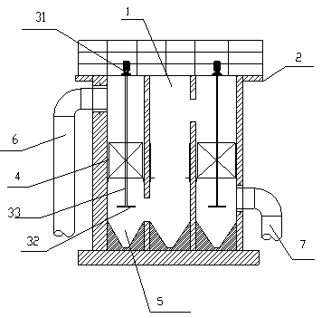
[0012] like figure 1 As shown, a grid stirring flocculation reaction equipment, the grid flocculation reaction equipment is formed by a number of shafts 1 connected in series, the top of the shaft 1 is provided with a corridor type cover plate 2, and every 1-3 rows of vertical shafts 1 are provided in the straight ditch. There is a mixer and several layers of grid packing 4, which increases the particle collision in the raw water under the constant stirring and grid hydraulic action, provides more favorable conditions for flocculation, and shortens the flocculation time at the same time. Holes are staggered on the wall and the bottom to make the water flow up and down until the outlet. The mixer is composed of a stirring motor 31, a stirring shaft 33 and a stirring impeller 32. The stirring motor 31 is set on the corridor-type cover plate 2 on the top and passes thro...


PUM


Abstract

The invention discloses a grid stirring flocculation reaction device. The grid stirring flocculation reaction device is composed of a plurality of vertical shafts via series connection; the tops of the vertical shafts are provided with a cover plate; the straight groove of every 1 to 3 rows of the vertical shafts is provided with a stirring machine and a plurality of layers of a grid filling material; each stirring machine is composed of a stirring motor and stirring blades; the stirring motors are arranged on the corridor-type cover plate arranged on the tops of the vertical shafts; the grid filling material is penetrated by stirring shafts; the stirring blades are connected with the stirring motors via the stirring shafts. The grid stirring flocculation reaction device is low in head loss and excellent in effects; effective energy consumption ratio is increased, so that needed flocculation time is shortened, and pond volume is reduced; the grid stirring flocculation reaction device is simple in structure; management, installation, and maintenance are convenient; impact resistance is excellent; water flow conditions are improved greatly; pond bottom sludge deposition is not easily caused; growth of algae on grids, and blocking of grid meshes are not easily caused because of continuous stirring.

Description

technical field [0001] The invention relates to a sewage treatment equipment, in particular to a grid stirring flocculation reaction equipment. Background technique [0002] The flocculation reaction process in the traditional water treatment process is a unit purification process centered on the formation of flocs, and its effect is determined by the chemical action of the flocculant and the physical action of the flocculation reaction facility. There are two types of mechanical flocculation reaction facilities and hydraulic flocculation reaction facilities, and the grid flocculation tank and mechanical flocculation tank are the typical forms of these two reaction facilities. In the grid flocculation tank, raw water and chemicals are mixed and formed by hydraulic flocculation equipment. Large and dense solid flocs visible to the naked eye, the mechanical flocculation tank uses the motor to drive the agitator through the deceleration device to stir the water; but there are m...

Claims


Application Information

Patent Timeline
Patent Type & Authority Applications(China)
IPC IPC(8): C02F1/52
Inventor 季献华周稳全李武林苏海娟郭涛徐俊秀章雄曹陈永邹伟伟
Owner JIANGSU JINGYUAN ENVIRONMENTAL PROTECTION
Why Eureka
Try Eureka