Rack type bridge expansion device

An expansion device and rack-type technology, applied in the field of bridge expansion joints, to achieve the effect of comfortable vehicle operation, strong three-dimensional deformation ability, and small impact force

Active Publication Date: 2015-09-30
CHENGDU XINZHU ROAD & BRIDGE MASCH CO LTD
View PDF5 Cites 5 Cited by
  • Summary
  • Abstract
  • Description
  • Claims
  • Application Information

AI Technical Summary

Problems solved by technology

[0006] The purpose of the present invention is to provide a rack-type bridge expansion device with stable operation, low impact force, low cost, and strong ability to adapt to the three-dimensional deformation of the bridge, so as to solve the technical problems of the existing bridge expansion device

Method used


Image

  • Rack type bridge expansion device
  • Rack type bridge expansion device
  • Rack type bridge expansion device

Examples


Embodiment

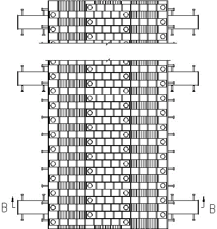
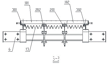
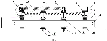
[0042] Such as Figure 1-5 As shown, a rack type bridge expansion device includes rack 1, H-shaped middle beam 2, H-shaped side beam 3, displacement box 6, cross beam 7, compression spring I5, support I8, compression spring II10, support II9, Sliding frame 11, waterproof rubber strip 13 and bolt 18; its specific structure is as follows:

[0043] The displacement box 6 is anchored to the beam end of the bridge through concrete pouring, and plays a role of fixing the expansion device and connecting to the expansion joint of the bridge.

[0044] The inner cavity of the displacement box 6 is provided with a compression spring I5 and a support I8, and both ends of the cross beam 7 are pre-compressed in the displacement box 6 through the compression spring I5 and the support I8; the H-shaped side beam 3 and the displacement box 6 are fixed as a whole ; In this way, the H-shaped side beam 3 can be fixed to prevent it from slipping.

[0045] The inner cavity of the sliding frame 11 is prov...


PUM


Abstract

The invention discloses a rack type bridge expansion device which comprises racks, an anchoring component, a displacement box, a cross beam, an H-shaped middle beam, an H-shaped lateral beam, a pressure spring I, a support I, a pressure spring II, a support II, a sliding frame and a waterproof adhesive tape, wherein the two ends of the cross beam are pre-pressed in the displacement box through the pressure spring I and the support I; the sliding frame is pre-pressed on the cross beam through the pressure spring II and the support II; the H-shaped lateral beam is integrally fixed with the displacement box; the H-shaped middle beam and the sliding frame are integrally connected through a bolt; the H-shaped middle beam can move by following the sliding of the sliding frame on the cross beam; the racks are arranged in a staggered form; one ends of the racks are pre-pressed on the H-shaped middle beam through the bolts while the other ends are pre-pressed on the H-shaped lateral beam through the bolts. The H-shaped middle beam is in sliding connection with the cross beam through the sliding frame, so that the displacement can be realized by the rack type bridge expansion device. The rack type bridge expansion device has the advantages of stable running, small effect caused by impact force, low cost and strong capability of adapting to three-dimensional deformation of the bridge.

Description

Technical field [0001] The invention relates to a rack type bridge expansion device, which is particularly suitable for concrete beams and steel box beam bridges, and belongs to the technical field of bridge expansion joints. Background technique [0002] With the country's gradual increase in the scale of highway and bridge construction, large-span bridges are increasing day by day. As a key component of the bridge, the bridge expansion device must not only meet the expansion and contraction caused by the temperature change of the bridge superstructure, but also meet the needs of the three-dimensional displacement movement of the beam end caused by constant and live loads. At the same time, the existing "heavy load, high density" traffic conditions put forward high requirements on the reliability of the use of bridge expansion devices. [0003] At present, there are two types of bridge expansion devices: modular expansion devices and comb-type expansion devices, which have their ...

Claims


Application Information

Patent Timeline
Patent Type & Authority Patents(China)
IPC IPC(8): E01D19/06
Inventor 焦洪林岳军罗炯何云伟
Owner CHENGDU XINZHU ROAD & BRIDGE MASCH CO LTD
Why Eureka
Try Eureka