Residue-holding float bowl structure for drainage system

A buoy structure and drainage system technology, which is applied in water/sewage treatment, water/sludge/sewage treatment, grease/oily substance/float removal device, etc., can solve the problem of easy blockage of the filter screen, and improve the slag blocking effect. , Simple structure, convenient installation effect

Active Publication Date: 2014-06-11
WUHAN SHENGYU DRAINING SYST
View PDF7 Cites 3 Cited by
  • Summary
  • Abstract
  • Description
  • Claims
  • Application Information

AI Technical Summary

Problems solved by technology

[0005] The present invention adopts the buoy structure for slag blocking. A part of the hollow buoy is submerged below the water surface, and the other part floats above the water surface. When the water flows through the buoy, the floating objects in the water are intercepted by the buoy, and the water flows out from the bottom of the buoy. This structure It solves the problem that the filter screen is easily blocked in the prior art, and it is no longer necessary to frequently wash and maintain the scum blocking equipment; and the scum intercepted by the buoy structure has a larger size range, that is, the scum is intercepted more thoroughly, The effect of slag blocking is improved; the hydraulic automatic control slag blocking of this structure is simple in structure, convenient in installation, good in manufacturability, safe and reliable

Method used


Image

  • Residue-holding float bowl structure for drainage system
  • Residue-holding float bowl structure for drainage system
  • Residue-holding float bowl structure for drainage system

Examples


Embodiment Construction

[0012] The present invention will be further described in detail below in conjunction with the accompanying drawings to facilitate a clearer understanding of the present invention, but they do not limit the present invention.

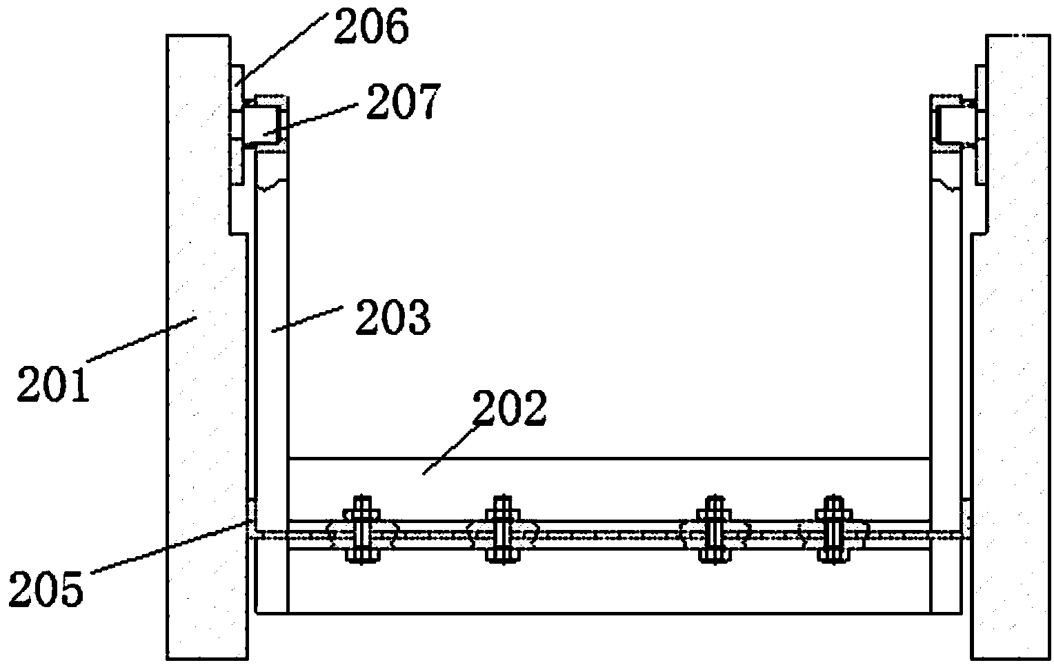
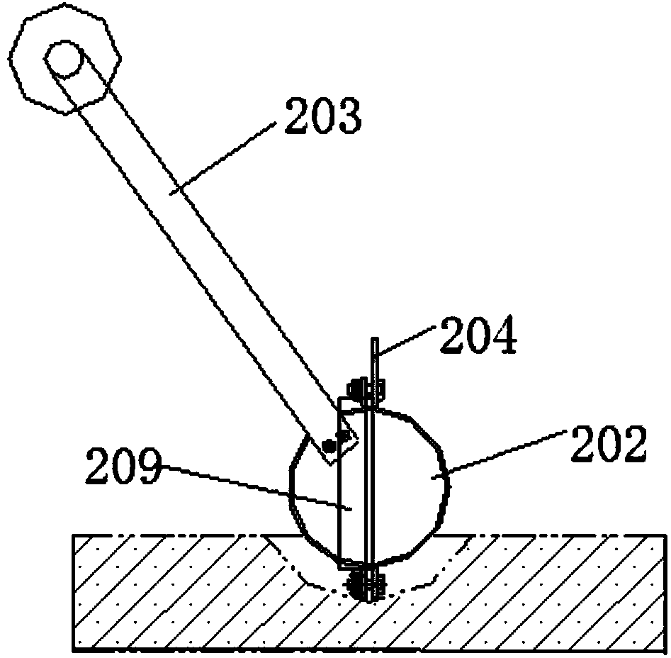
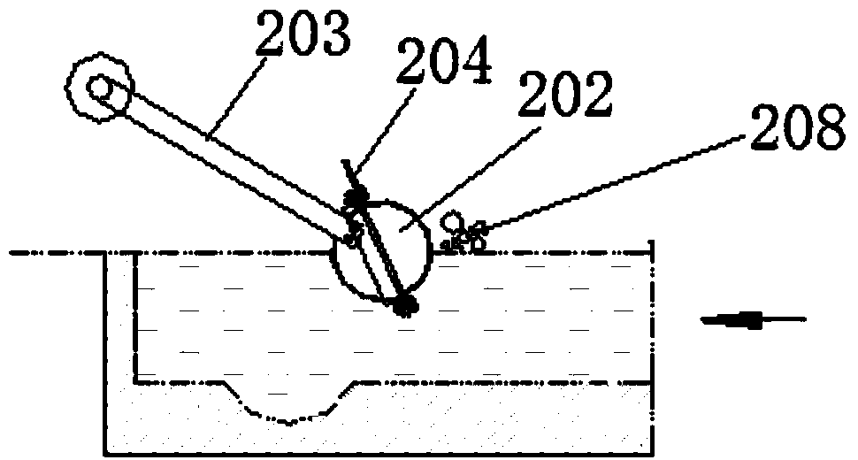
[0013] Such as figure 1 , figure 2 As shown, a slag-blocking buoy structure for a drainage system includes a pool body 201, and a cylindrical buoy 202 is arranged inside the pool body 201. The buoy 202 is hollow and has two ends closed, and the buoy 202 is in two halves structure, the two halves are connected by bolts, and a flexible sealing plate 205 is sandwiched between them. The two ends of the buoy 202 are leaked away, and the buoy 202 is placed vertically in the direction of water flow and the length spans the two side walls of the pool body 201. The end faces are connected by bolts, the two side walls of the pool body 201 are provided with fixing plates 206, and the ends of the rotating arms 203 are respectively hinged on the fixing plates 206...


PUM


Abstract

The invention discloses a residue-holding float bowl structure for a drainage system. The structure comprises a tank body, wherein a cylindrical float bowl is arranged in the tank body and is in a hollow shape, two end planes of the tank body are sealed, and the float bowl is flatly placed to be vertical to a water current direction and the length of the float bowl stretches across the two side walls of the tank body, and rotary arms are fixedly connected on the two end planes of the float bowl and are respectively hinged onto the side walls of the tank body. When the float bowl structure is adopted to hold residues, a part of the hollow float bowl is immersed below the water surface, and the other part of the hollow float bowl floats above the water surface, and floating objects are blocked through the float bowl when the water flows through the float barrel, and the water discharges from the bottom of the float bowl, so that the structure solves the problem that a filter screen can be easily blocked in the prior art, and the residue-holding equipment are not needed to wash and maintain; furthermore, the size range of the floating residues held up by the floater structure is larger, the floating residues are held up more thoroughly, so that the residue-holding effect can be improved; in addition, the residue-holding can be automatically controlled through hydraulic power, and the float bowl structure is simple in structure, convenient to install, good in technology, and safe and reliable to use.

Description

technical field [0001] The invention relates to drainage system equipment, in particular to a slag-retaining buoy structure used in the drainage system. Background technique [0002] In the process of draining the drainage pipe network to the natural water body, the scum in it needs to be removed to prevent the scum from entering the natural water body. Usually, the filter screen is set in the interception well to intercept the floating matter, and the filter screen scum blocking effect Well, the scum of different sizes can be intercepted by setting the grid size reasonably. However, the use of a filter screen to block scum is likely to cause the filter screen to be clogged due to the accumulation of debris, and frequent cleaning and maintenance are required; Scum can't quite have both. Contents of the invention [0003] The object of the present invention is to provide a slag-retaining buoy structure for a drainage system, which has a good slag-retaining effect and no cl...

Claims


Application Information

Patent Timeline
IPC IPC(8): E03F5/14
Inventor 周超何锐
Owner WUHAN SHENGYU DRAINING SYST
Why Eureka
Try Eureka