Phase locking loop with current compensation mechanism and method thereof

A technology of phase-locked loop and current compensation, applied in the direction of electrical components, automatic power control, etc., can solve the problem of large phase difference of phase-locked loop, achieve the effect of changing accuracy and simple structure

Active Publication Date: 2014-06-11
HIMAX TECH LTD
View PDF4 Cites 3 Cited by
  • Summary
  • Abstract
  • Description
  • Claims
  • Application Information

AI Technical Summary

Problems solved by technology

[0008] In view of the above-mentioned problems in the prior art, one of the objects of the present invention is to provide a phase-locked loop with a current compensation mechanism to solve the phase-locked loop caused by the mismatch of the manufacturing process or other reasons in the prior art. The phase difference between the output signal of the loop and the reference signal is too large

Method used


Image

  • Phase locking loop with current compensation mechanism and method thereof
  • Phase locking loop with current compensation mechanism and method thereof
  • Phase locking loop with current compensation mechanism and method thereof

Examples


Embodiment Construction

[0057]Embodiments of the phase-locked loop with a current compensation mechanism and the phase-locking method thereof according to the present invention will be described below with reference to the relevant drawings. For ease of understanding, the same elements in the following embodiments are described with the same symbols. .

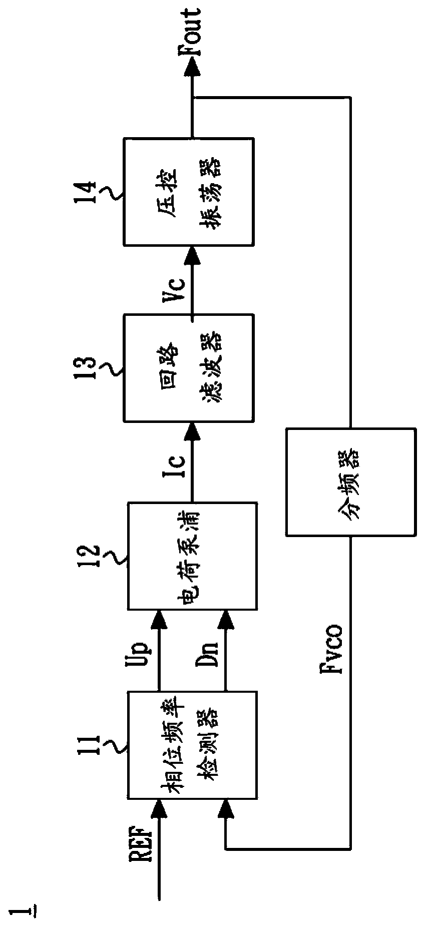
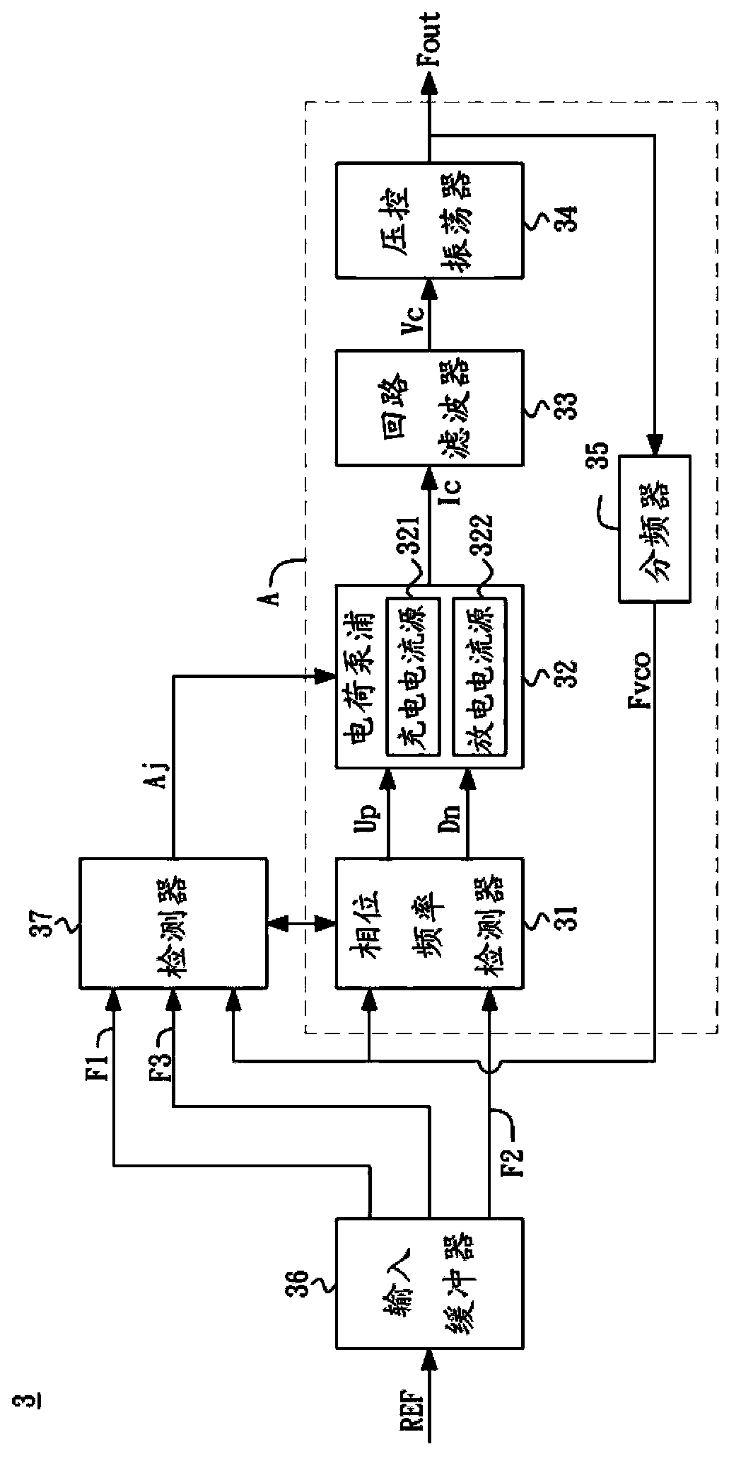
[0058] see image 3 , which is a block diagram of the first embodiment of the phase-locked loop with current compensation mechanism of the present invention. As shown, the PLL 3 may include an input buffer 36, a detector 37 and figure 1 The charge-pumped phase-locked loop A mentioned above. The charge-pumped phase-locked loop A may include a phase frequency detector (Phase Frequency Detector, PFD) 31, a charge pump (Charge Pump) 32, a loop filter (Loop Filter) 33, a voltage-controlled oscillator (Voltage-controlled Oscillator) , VCO) 34 and frequency divider (Divider) 35.

[0059] The input buffer 36 can include multiple buffers, the input buffer...


PUM


Abstract

The invention discloses a phase locking loop with a current compensation mechanism and a method of the phase locking loop. The phase locking loop comprises an input buffer, an electric charge pumping type phase locking loop body, a detector and a locking judgment device. The input buffer can receive a reference signal so as to generate a first signal, a second signal and a third signal, and the phase delay of the second signal is larger than that of the first signal but smaller than that of the third signal. The locking judgment device can start the detector through a starting signal after detecting that the electric charge pumping type phase locking loop body locks phase difference between a feedback signal and the second signal. The detector executes a sampling program on the feedback signal according to the first signal and the third signal, and an adjustment signal is output to the electric charge pumping type phase locking loop body according to the sampling result so as to adjust the phase position of the feedback signal to be between the first signal and the third signal.

Description

technical field [0001] The invention relates to a phase-locked loop with a current compensation mechanism, in particular to a phase-locked loop that can fine-tune the phase of the feedback signal after the phase difference between the reference signal of the phase-locked loop and the feedback signal is locked, so as to further reduce the A phase-locked loop for the phase difference between the reference signal and the feedback signal. Background technique [0002] Phase Locked Loop (Phase Locked Loop, PLL) is a very common circuit nowadays, which is widely used in electronics, communications and other fields. The main function of the PLL is to make the phase of the input reference signal and the output clock signal The difference can be maintained within a fixed range, thereby achieving the effect of locking the phase difference between the input reference signal and the output clock signal. However, due to the improvement of manufacturing process technology, the problems f...

Claims


Application Information

Patent Timeline
Patent Type & Authority Applications(China)
IPC IPC(8): H03L7/085
Inventor 林威硕
Owner HIMAX TECH LTD
Why Eureka
Try Eureka