
Apparatus for processing plastic material

A technology for plastic materials and waste plastics, applied in the fields of plastic recycling, transportation and packaging, recycling technology, etc., can solve the problems of narrowing of the cross section of the entry hole, poor entry characteristics, loss of throughput, etc.

Active Publication Date: 2014-06-11
EREMA ENG RECYCLING MASCH & ANLAGEN GMBH
View PDF9 Cites 0 Cited by
  • Summary
  • Abstract
  • Description
  • Claims
  • Application Information

AI Technical Summary

Problems solved by technology

This in turn allows material to accumulate in this area, narrowing the cross-section of the entry hole and causing worse entry characteristics and subsequent loss of throughput
Furthermore, melting occurs due to the increased feed pressure in this region, whereby the problems mentioned at the outset arise again

Method used


Image

  • Apparatus for processing plastic material
  • Apparatus for processing plastic material
  • Apparatus for processing plastic material

Examples


Embodiment Construction

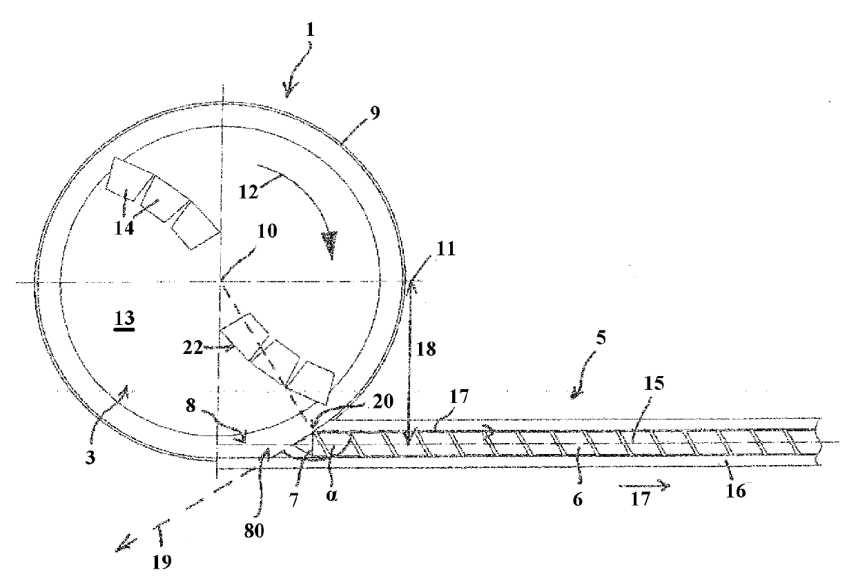
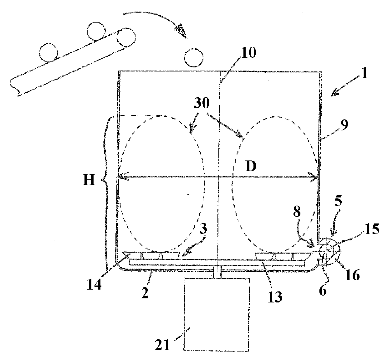
[0058] exist figure 1 and figure 2 The advantageous shredding compressor-extruder-combination for preparing or recycling plastic material shown in has a cylindrical container or shredding compressor or shredder 1 with a flat horizontal The bottom surface 2 and the vertical cylindrical covering-shaped side walls 9 oriented standardly thereto.

[0059] At a slight distance from the base 2, up to about 10 to 20% of the height of the side walls 9 - measured from the base 2 to the uppermost edge of the side walls 9 - and possibly less are arranged parallel to the base 2 Oriented flat carrier plate or tool holder 13 , which can be rotated in the direction of rotation or movement marked with arrow 12 about a central rotational axis 10 , which is at the same time the central central axis of container 1 . The carrier plate 13 is driven by a motor 21 located below the container 1 . Arranged on the upper side of the carrier plate 13 are knives or tools 14 , for example cutting knives...


PUM


Abstract

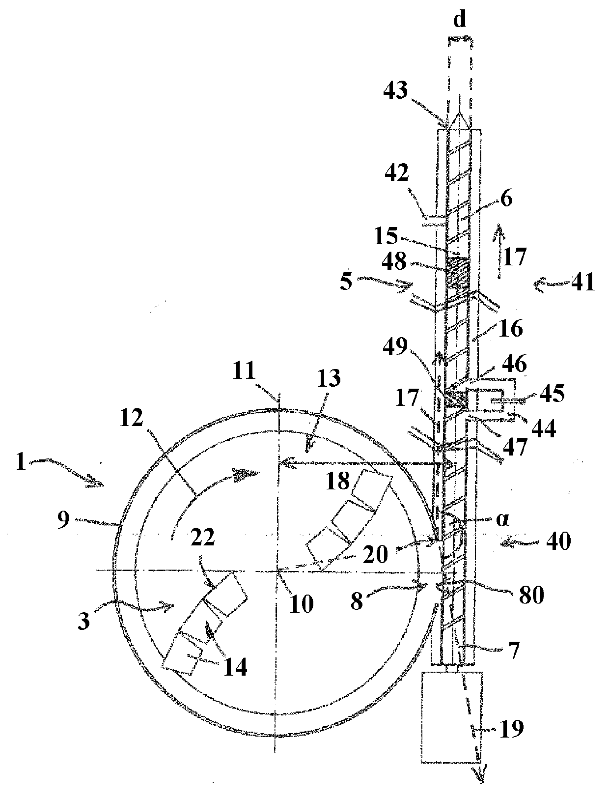
The invention relates to an apparatus for preprocessing and subsequently conveying or plasticizing plastics, comprising a container (1) with a mixing and / or comminuting tool (3) that can rotate about a rotational axis (10), wherein an opening (8) is formed in a lateral wall (9) through which the plastic material can be discharged, and a conveyor (5) is provided with a screw (6) rotating in a housing (16). The housing (16) is divided into two chambers (40, 41), the front chamber (40) of which comprising the feed opening (80) and the rear chamber (41) at least one degassing opening (42), both chambers (40, 41) being connected to each other by a channel (44) in which a melt filter (45) is arranged. The invention is characterized in that the imaginary extension of the longitudinal axis (15) of the conveyor (5) passes by the rotational axis (10) counter the conveying direction (17), wherein the longitudinal axis (15) is on the outlet side offset by a distance (18) in relation to the radial (11) that is parallel to the longitudinal axis (15). The length (L) of the screw (6) in the front chamber (40) lies in the range of 10 to 40 times the nominal diameter (d) of the screw (6), and the distance from the opening (46) of the channel (44) into the rear chamber (41) to the degassing opening (42) lies in the range of 1.5 to 15 times the nominal diameter (d) of the screw (6).

Description

technical field [0001] The invention relates to a device according to the preamble of claim 1 . Background technique [0002] Methods and devices of a similar type have been known from the prior art for a long time. It is disclosed that the plastic material to be recycled is first prepared in a shredder compressor at elevated temperature and optionally with vacuum application, then melted in an extruder and the melt filtered, then degassed and finally pelletized, for example. Devices for carrying out this method are known, for example, from EP 123 771 B, EP 390 873 B or AT 396 900 B. [0003] There are also numerous methods and devices for optimizing individual steps, such as degassing the melt. For example, a pressure-free zone can be formed in front of the vent hole, thus ensuring reliable degassing of the plastic material. There are also numerous embodiments of melt filters for removing solid foreign matter and / or residual polymer that has not melted. [0004] All of ...

Claims


Application Information

Patent Timeline
Patent Type & Authority Applications(China)
IPC IPC(8): B29B13/10B29B17/04B29C47/58B29C47/68B29C47/76B02C18/08B01F15/02B29C48/395B29C48/40B29C48/50B29C48/67B29C48/76
CPCB29C47/40B29B13/10B02C18/086B29C47/385B29C47/6018B29C47/1018B02C18/12B29B17/0412B29C47/64B29C47/76B29B2017/048B29B7/66B29C47/585B01F15/0289B29C47/68B29K2105/26B29C47/0011B29B17/0026B29C47/1027B29B17/04Y02W30/62B29C48/04B29C48/53B29C48/67B29C48/397B29C48/40B29C48/69B29C48/76B29C48/287B29C48/288B29C48/501B01F35/754551B29B7/42B29B7/48B29B7/60B29B7/885B01F35/71B02C18/08
Inventor K.菲奇廷格M.哈克尔
Owner EREMA ENG RECYCLING MASCH & ANLAGEN GMBH
Learn More