Supercharge Your Innovation With Domain-Expert AI Agents!

Supporting plate of stamping die and its installation structure

A technology for stamping dies and mounting structures, applied in the field of stamping dies, can solve the problems of increased weight of automobile stamping dies, increased design and manufacturing costs, etc., and achieves the effects of light weight, easy material acquisition, and small thickness

Active Publication Date: 2015-10-28
BEIQI FOTON MOTOR CO LTD
View PDF5 Cites 0 Cited by
  • Summary
  • Abstract
  • Description
  • Claims
  • Application Information

AI Technical Summary

Problems solved by technology

Therefore, when the upward movement of the cast iron plate 2' is large, the thickness of the cast iron plate 2' is required to be relatively large, and corresponding to different automobile panels, it is necessary to configure the cast iron plate 2' with corresponding thickness specifications , resulting in an increase in the weight of the automotive stamping die and an increase in design and manufacturing costs

Method used


Image

  • Supporting plate of stamping die and its installation structure
  • Supporting plate of stamping die and its installation structure
  • Supporting plate of stamping die and its installation structure

Examples


Embodiment Construction

[0025] The specific embodiments of the present invention will be described in detail below with reference to the accompanying drawings. It should be understood that the specific embodiments described herein are only used to illustrate and explain the present invention, and not to limit the present invention.

[0026] In the present invention, if there is no explanation to the contrary, the orientation words used such as "up, down, top, bottom" are usually for the directions shown in the drawings or for vertical, vertical or gravity directions The terms used to describe the mutual positional relationship of the components mentioned above.

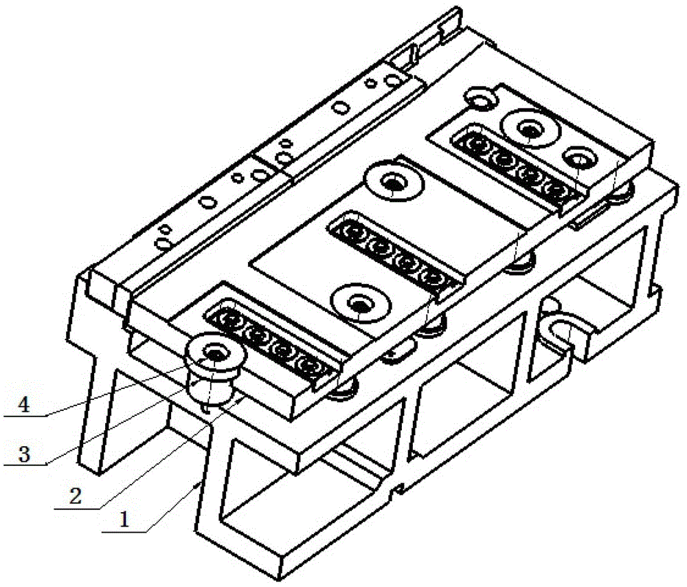
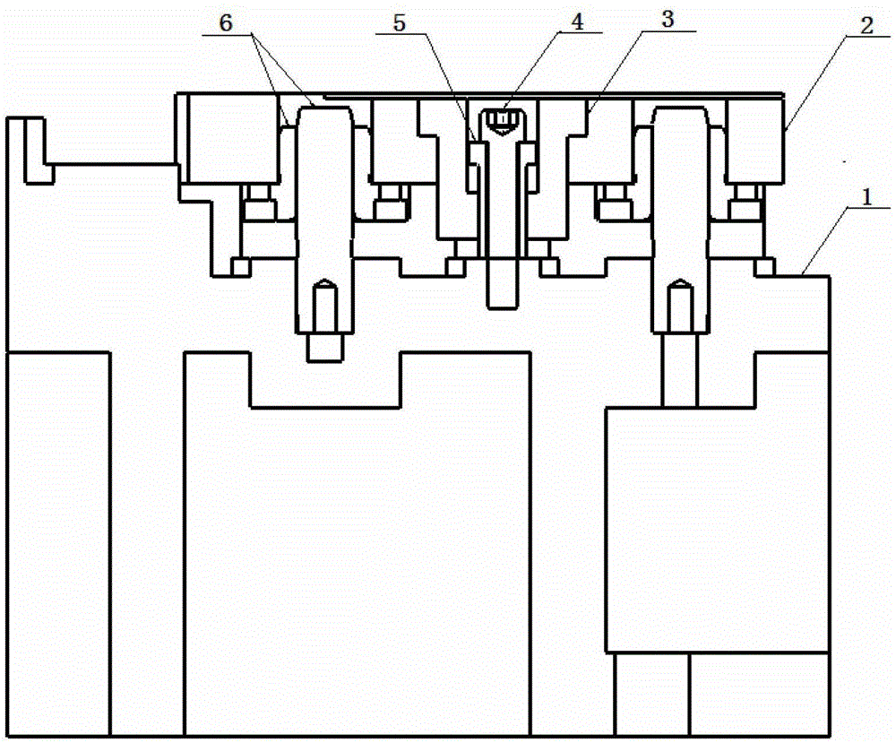
[0027] Such as figure 1 with figure 2 As shown, the present invention provides a support plate of a stamping die. The support plate 2 is respectively embedded with bushings 3 at different positions, and the axial direction of each bush 3 is along the thickness direction of the support plate 2. One end of sleeve 3 does not exceed the supporting...


PUM


Abstract

The invention discloses a retainer plate of a punching die and an installation structure thereof. Linings (3) are embedded in the retainer plate (2) at different positions and stretch out of the retainer plate. A step hole is formed in a hollow cavity of each lining, a small cavity of the step hole is formed in the stretching portion of the lining, and a step interface is located in the stretching portion. The retainer plate is installed on the upper surface of a lower die body (1), a guide column (6) and an elastic element are arranged between the retainer plate and the upper surface of the lower die body, and a limit piece (4) is arranged in each lining of the retainer plate. Each limit piece comprises a limit portion and a rod portion, the limit portion is arranged in a corresponding large cavity and cannot penetrate the corresponding small cavity, the limit portion cannot exceed the retaining face of the retainer plate, and the rod portion penetrates the corresponding small cavity to stretch out to be fixedly connected onto the lower die body. The retainer plate can be made of a thin steel plate which can be combined with the linings to replace heavy cast iron plates to achieve large stroke limit of upward movement of the retainer plate. The retainer plate is small in thickness, light in weight and good in generality. Materials are easy to take.

Description

Technical field [0001] The invention relates to a stamping die, in particular to a supporting plate of the stamping die and an installation structure thereof. Background technique [0002] The development cycle and development cost of stamping dies for automobile panels have become the main factors affecting the development cycle and cost of the entire vehicle. Such as image 3 As shown, the left part of the figure shows the lower die body 1 of the automobile stamping die and the cast iron plate 2'which is installed on the lower die body 1 as a pallet. The cast iron plate 2'and the lower die body 1 There are elements such as guide posts and springs. In order to restrict the cast iron plate 2'from moving upwards beyond the set stroke, a stepped through hole is provided on the cast iron plate 2', and the safety screw or bolt as a limiting element passes through the through hole on the cast iron plate 2' And firmly connected to the lower mold body 1. When the cast iron plate 2'mov...

Claims


Application Information

Patent Timeline
Patent Type & Authority Patents(China)
IPC IPC(8): B21D37/10
Inventor 孙延春
Owner BEIQI FOTON MOTOR CO LTD
Features
  • R&D
  • Intellectual Property
  • Life Sciences
  • Materials
  • Tech Scout
  • Unparalleled Data Quality
  • Higher Quality Content
  • 60% Fewer Hallucinations
Learn More